
Motor copper rotor die casting device and die casting method

A copper rotor and rotor technology, applied in the field of motor copper rotor die-casting devices, can solve the problems of motor noise, large mold damage, low copper rotor filling rate, etc., and achieve the effects of improving work efficiency, reducing mold heat dissipation, and excellent filling rate

Active Publication Date: 2018-08-24
浙江钜丰科技有限公司
View PDF9 Cites 3 Cited by
  • Summary
  • Abstract
  • Description
  • Claims
  • Application Information

AI Technical Summary

Problems solved by technology

Using this technical solution, although it can effectively prevent the oxidation of pure copper and copper alloys during the smelting process, and the mold is easy to disassemble and replace, it has its disadvantages: 1. When the copper rod is loaded into the furnace for smelting, the intermediate frequency furnace needs to be heated first Raise to 20KW, and then upgrade to 40KW smelting after the copper rod turns red. The copper rod needs to be preheated. The whole process consumes time and energy, which increases the production cost of the enterprise; 2. The impurities in the copper melt cannot be cleaned in time Go out and die-cast the copper melt, the impurities in it will cause cracks at the end of the copper rotor, and the filling rate of the copper rotor is low, and the motor will generate noise during operation; 3. The mold preheating temperature is too high, Great damage to the mold, energy consumption, and in the subsequent demoulding process of the copper rotor, the copper melt is easy to stick to the mold, making demoulding difficult and damaging the copper rotor

Method used


Image

  • Motor copper rotor die casting device and die casting method
  • Motor copper rotor die casting device and die casting method
  • Motor copper rotor die casting device and die casting method

Examples


Embodiment

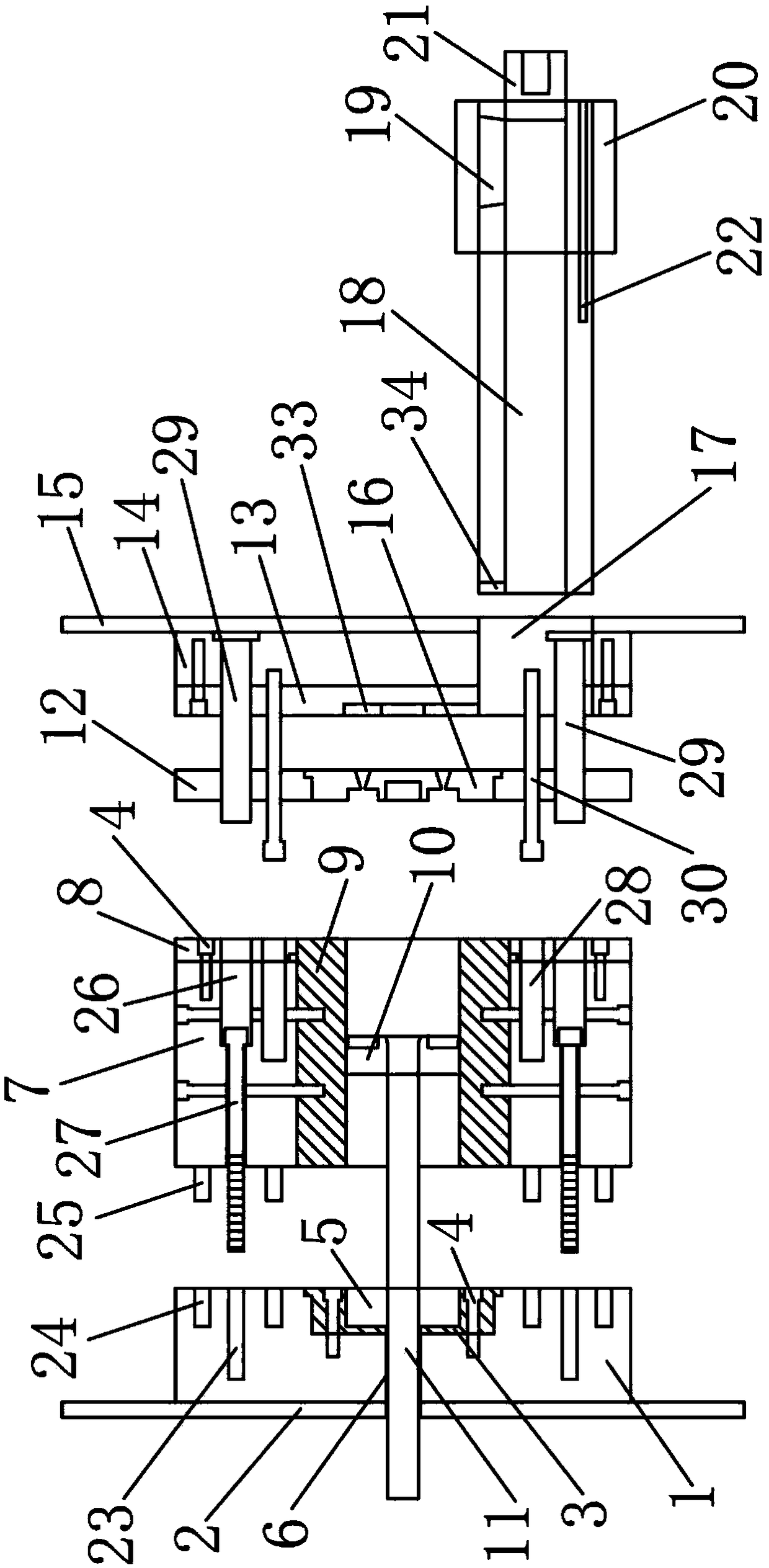
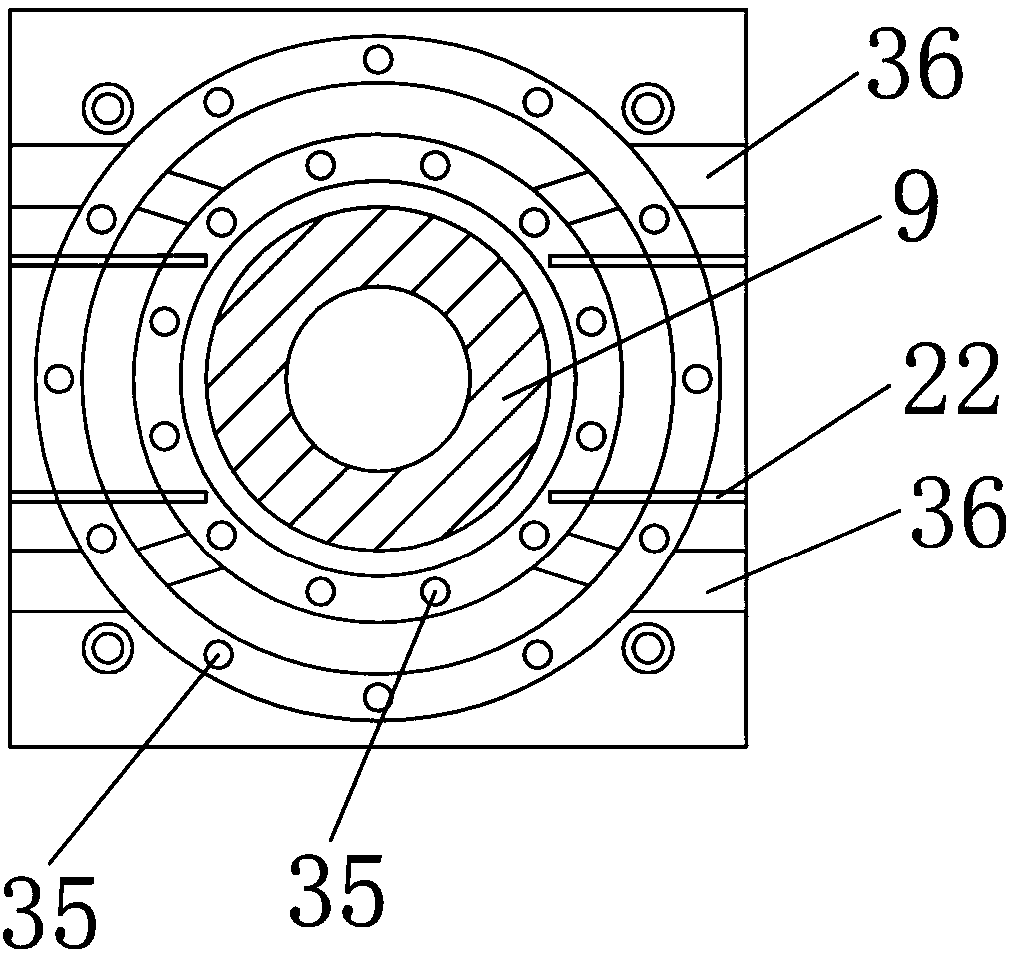
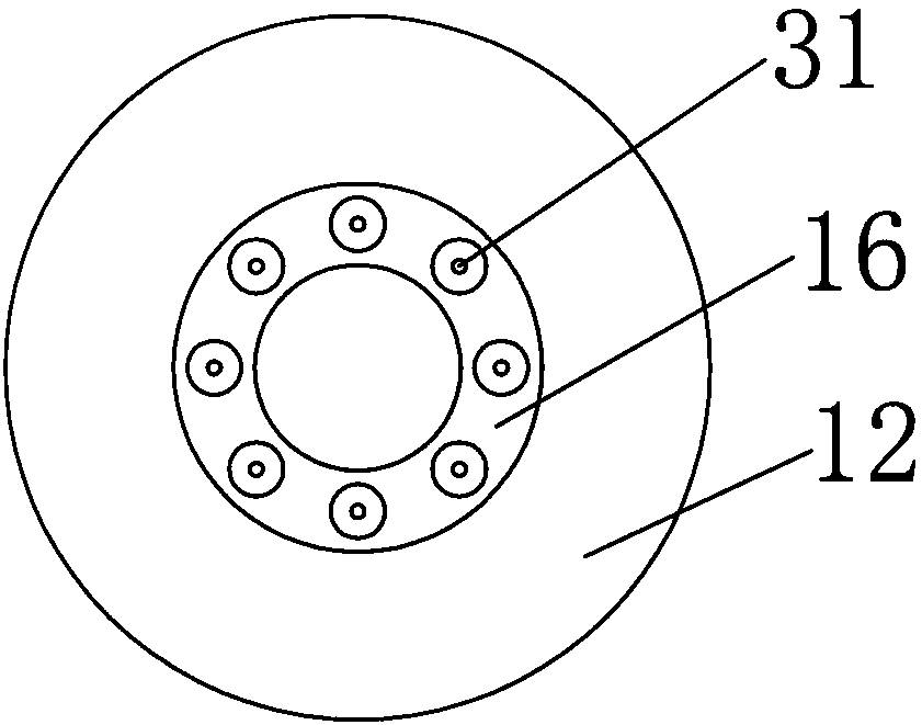
[0022] Embodiment: a kind of motor copper rotor die-casting device, such as Figure 1-Figure 4As shown, it includes a low-frequency induction furnace and a die-casting machine. The heating power of the low-frequency induction furnace is 0-50KW. The die-casting machine includes a front mold assembly, a middle mold assembly, a rear mold assembly and an injection mold assembly. The rear mold Components, middle mold components, front mold components, and injection mold components are arranged in sequence and assembled together; the rear mold component includes a rear mold frame and a rear mold heat shield, and the rear mold heat shield is fixedly arranged on the left side of the rear mold frame. side, the right side of the rear mold base is provided with a mold base, the mold base is coaxial with the rear mold base, and the mold base is fixedly connected with the rear mold base through a screw, and a groove is arranged in the mold base, and the The bottom of the groove is provided...


PUM


Abstract

The invention discloses a motor copper rotor die casting device and a die casting method, and belongs to the technical field of non-ferrous metal smelting and rolling processing. The motor copper rotor die casting device comprises a low-frequency induction furnace and a die casting machine. The heating power of the low-frequency induction furnace is 0-50 KW, the die casting machine comprises a front die assembly, a middle mold assembly, a rear mold assembly and a pressing mold assembly; and the front mold assembly, the middle mold assembly, the rear mold assembly and the injection mold assembly are sequentially arranged and spliced and combined. According to the motor copper rotor die casting device and the die casting method, a middle mold frame and a rear mold frame are fixedly connectedthrough screw thread connection, the middle mold frame and the rear mold frame are connected through limiting rods, limiting holes, square columns and bolt holes, and the mold frames are convenient to detach; and meanwhile, the produced castings are free of cracks, the filling rate is excellent, the adverse defects such as sticky mold are avoided, and a motor of a pure copper rotor of the die casting can reach the ultrahigh energy efficiency grade of IE 4.

Description

technical field [0001] The invention belongs to the technical field of nonferrous metal smelting and calendering, and in particular relates to a die-casting device and a die-casting method for a copper rotor of a motor. Background technique [0002] The cast copper rotor is a new type of motor rotor with copper as the conductive matrix. In the prior art, aluminum is generally used as the conductive matrix, but the conductivity of aluminum is only 60.7% of copper, and the resistivity is about 1.6 times that of copper. By using cast copper rotors instead of cast aluminum rotors, the total loss of the motor can be significantly reduced, thereby improving the overall efficiency of the motor. Although cast copper rotors have many advantages, due to the difficulty of producing cast copper rotors, cast aluminum rotors are still widely used in electric motors. [0003] The invention patent with the patent number of 200710066135.8 discloses a die-casting method and die-casting devic...

Claims


Application Information

Patent Timeline
IPC IPC(8): B22D17/22B22D17/00
CPCB22D17/00B22D17/22B22D17/2218B22D17/2236B22D17/2272
Inventor 裘珂可
Owner 浙江钜丰科技有限公司
Learn More