
High-working-frequency ceramic-base micro-band band-pass filter

A band-pass filter, working frequency technology, applied in the field of filters, can solve the problem that the filter cannot meet the demand, etc., and achieve the effect of simple structure, easy processing, and reduced insertion loss

Inactive Publication Date: 2018-08-21
TIANJIN UNIV
View PDF2 Cites 4 Cited by
  • Summary
  • Abstract
  • Description
  • Claims
  • Application Information

AI Technical Summary

Problems solved by technology

[0002] With the development of modern weapons and equipment models, modern military weapons and equipment are updated so fast that traditional filters can no longer meet the needs.

Method used


Image

  • High-working-frequency ceramic-base micro-band band-pass filter
  • High-working-frequency ceramic-base micro-band band-pass filter
  • High-working-frequency ceramic-base micro-band band-pass filter

Examples


Embodiment Construction

[0021] In order to make the purpose, technical solutions and beneficial effects of the present invention clearer, the present invention will be further described in detail below in conjunction with the accompanying drawings and embodiments.

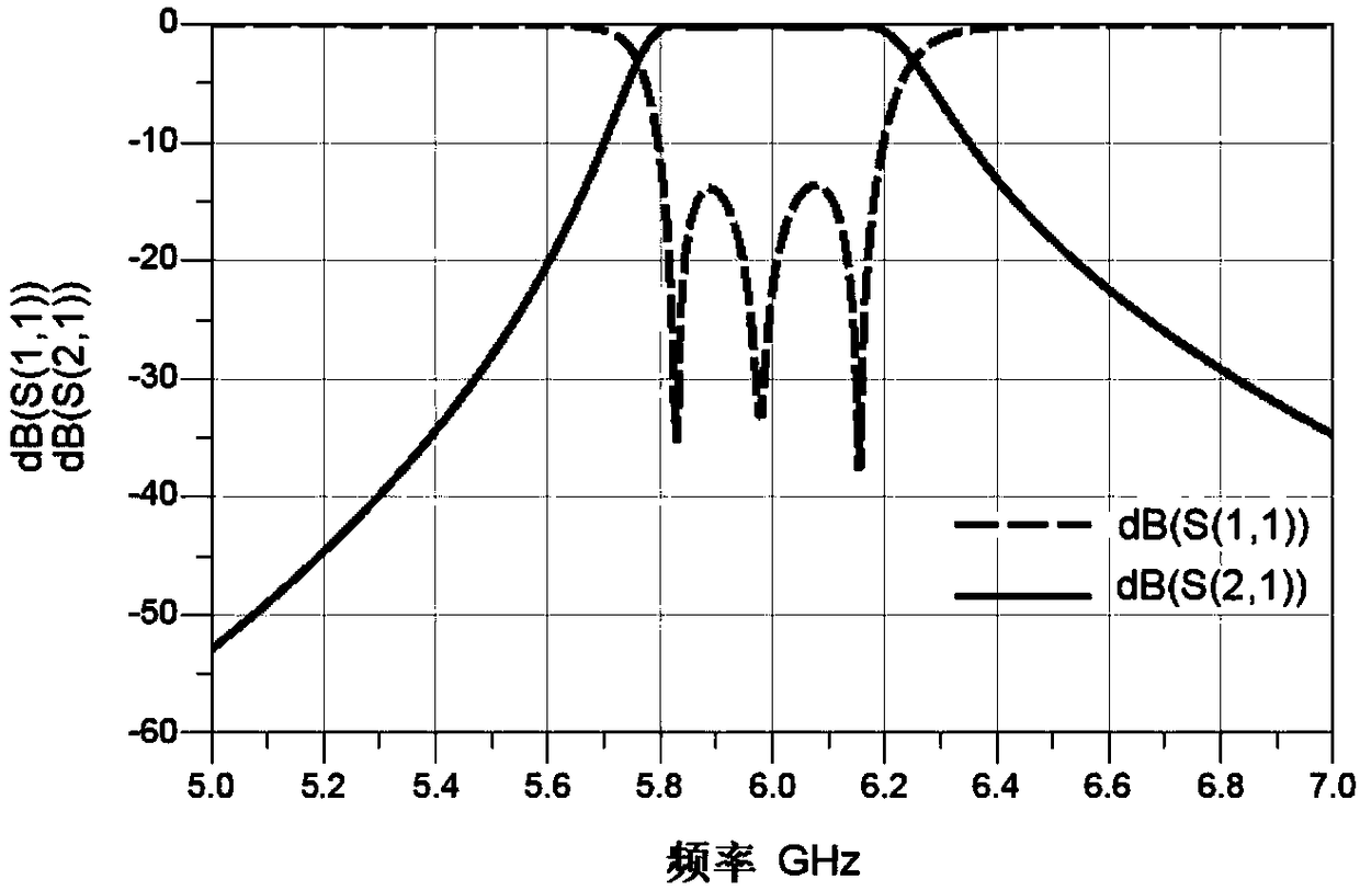
[0022] The planar structure of the microstrip bandpass filter of the present invention is as figure 1 , figure 2 As shown, conventional preparation methods and conventional raw materials are used for preparation.

[0023] The ceramic dielectric substrate is MgTiO 3 A ceramic substrate 9, the back of the ceramic substrate 9 is provided with a metal grounding plate 8;

[0024] An input feeder 1 is provided on the upper left of the front of the ceramic substrate 9, and an input parallel coupling line 3 and an input parallel coupling line 4 are provided on the inward side of the input feeder 1, and the input parallel coupling line 3 and the input parallel coupling line 4 are connected to the input feeder 1 The output feeder 2 is arranged ...


PUM


Abstract

The invention discloses a high-working-frequency ceramic-base micro-band band-pass filter. The high-working-frequency ceramic-base micro-band band-pass filter comprises a MgTiO3 ceramic substrate (9),and a metal grounding plate (8) is arranged on the back face of the MgTiO3 ceramic substrate (9); an input feeder (1) is arranged at the upper left portion of the front face of the MgTiO3 ceramic substrate (9), and an input parallel coupling line (3) and an input parallel coupling line (4) are arranged on one inward side of the input feeder (1); an output feeder (2) is arranged at the lower rightportion of the front face of the MgTiO3 ceramic substrate (9), and an output parallel coupling line (5) and an output parallel coupling line (6) are arranged on one inward side of the output feeder (2); an output parallel coupling line (7) is arranged in the middle of a connecting line between the input feeder (1) and the output feeder (2); the input feeder (1) and the output feeder (2) are micro-band lines with the characteristic impedance of 50 ohm, and are of parallel coupling feeding structures. According to the high-working-frequency ceramic-base micro-band band-pass filter, the size ofthe filter is decreased, insertion loss in a passband is reduced, higher harmonics can be effectively controlled, the center frequency of the pass band is easily controlled, the structure is simple, and processing is easy.

Description

technical field [0001] The invention relates to a filter, in particular to a microstrip bandpass filter with high operating frequency, small layout size and low insertion loss. Background technique [0002] With the development of modern weapons and equipment models, the replacement speed of modern military weapons and equipment is so fast that traditional filters can no longer meet the needs. Research on miniaturized and high-quality filters is conducive to breaking the international blockade on the development of high-reliability and high-power carrying microstrip line filters, and filling the gap in the development of high-quality microwave filters in China. It is of great significance to improve the performance level of my country's military electronic systems and electronic countermeasures. In recent years, especially the rapid popularization of 4G mobile communication and the close deployment of 5G mobile communication, there is an urgent need to develop filters with ...

Claims


Application Information

Patent Timeline
Patent Type & Authority Applications(China)
IPC IPC(8): H01P1/212
CPCH01P1/212
Inventor 李玲霞许振鹏于仕辉杜明昆乔坚栗
Owner TIANJIN UNIV
Learn More