Microstrip bandpass filter and design method thereof
A band-pass filter and filter technology, applied in the field of communication, can solve the problems of poor frequency selectivity and large size, and achieve the effects of small size, easy debugging, and simple design process
- Summary
- Abstract
- Description
- Claims
- Application Information
AI Technical Summary
Problems solved by technology
Method used
Image
Examples
Embodiment Construction
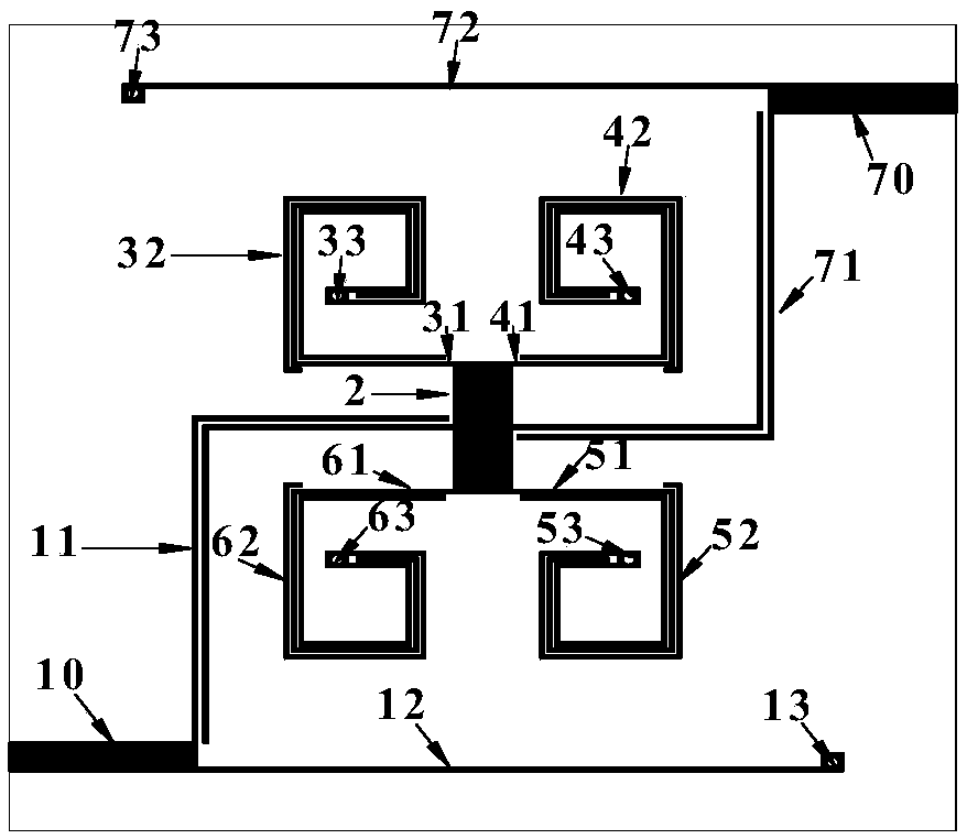
[0025] In order to embody the inventiveness and novelty of the present invention, the physical mechanism of the microstrip bandpass filter is deeply analyzed below. During the analysis, it will be explained in conjunction with the drawings and specific examples, but the implementation manner of the present invention is not limited thereto. Without loss of generality, the microstrip bandpass filter of the present invention is used to realize a bandpass frequency response, the center frequency is 2.34GHz, the relative bandwidth is 39%, and the in-band return loss is greater than 20dB. The impedance of the input and output feed lines was set to 50Ω. The ideal bandpass frequency response is as Figure 5 shown.
[0026]According to the design steps of the microstrip bandpass filter as mentioned above, the first step is to determine Figure 4 Individual element values of the lumped parameter equivalent circuit in . In this embodiment, it is calculated that: R S =R L =50Ω,K ...
PUM
 Abstract
Description
Claims
Application Information
 - R&D
- Intellectual Property
- Life Sciences
- Materials
- Tech Scout
- Unparalleled Data Quality
- Higher Quality Content
- 60% Fewer Hallucinations
Browse by: Latest US Patents, China's latest patents, Technical Efficacy Thesaurus, Application Domain, Technology Topic, Popular Technical Reports.
© 2025 PatSnap. All rights reserved.Legal|Privacy policy|Modern Slavery Act Transparency Statement|Sitemap|About US| Contact US: help@patsnap.com


