Eureka AIR delivers breakthrough ideas for toughest innovation challenges, trusted by R&D personnel around the world.

Direct buried cable joint insulation and waterproofing processing device and method

A technology of cable joints and waterproof treatment, which is applied in the direction of cable joints, cable installation, cable accessories, etc., can solve the problems of limited insulation and waterproof effect, high laying cost, high requirements, etc., achieve good waterproof effect, meet insulation performance and waterproof performance, good sealing effect

Pending Publication Date: 2018-08-17
GUANGDONG CONSTR ENG GRP
View PDF0 Cites 2 Cited by
  • Summary
  • Abstract
  • Description
  • Claims
  • Application Information

AI Technical Summary

Problems solved by technology

[0002] When laying direct-buried cables, since the cables are always charged, the intermediate joints connecting the two cables usually need to be insulated and waterproofed. The existing method is to crimp the two buried cables through the intermediate joints. Wrapped with epoxy resin, this treatment method has limited insulation and waterproof effects, and needs to be equipped with high-quality intermediate joints, and it is necessary to ensure that the soil where the cables are buried is dry and not easy to seepage, so as to avoid the degradation of the performance of the cable edge due to poor waterproofing. Breakdown occurs, but this method has high requirements for the laying environment and related accessories, and has the disadvantages of high laying cost and limited quality, so it is necessary to improve

Method used


Image

  • Direct buried cable joint insulation and waterproofing processing device and method
  • Direct buried cable joint insulation and waterproofing processing device and method
  • Direct buried cable joint insulation and waterproofing processing device and method

Examples


Embodiment

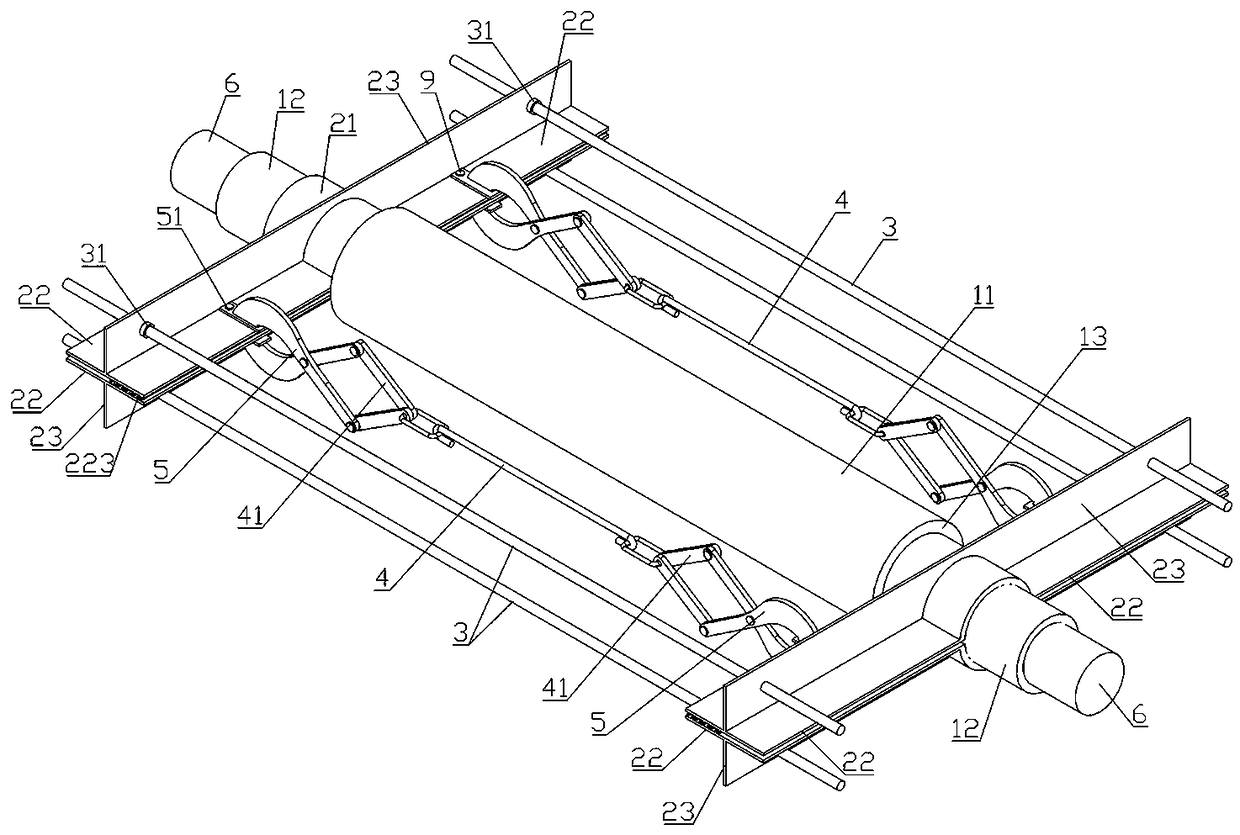
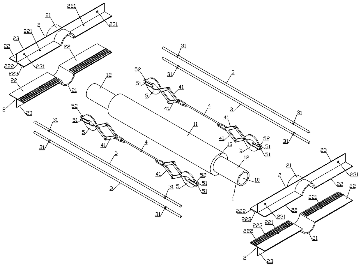
[0028] refer to figure 1 and figure 2 , a direct-buried cable joint insulation and waterproof treatment device, which includes an elastic outer sleeve 1, a pull device frame, a limit screw 3 and a device frame tension clamp.

[0029] The elastic outer sleeve 1 is a circular tubular structure with a through hole 10 in the center made of rubber material. The middle part of the elastic outer sleeve 1 has a main pipe portion 11 and two ends have end pipe portions 12. The pipe wall of the main pipe portion 11 is Thickening makes the end pipe portion 12 have a limiting boss 13 near the main pipe portion 11 .

[0030] The said pull device frame is formed by two half-pipe splints 2 oppositely arranged and fastened, and the middle part of said half-pipe splint 2 has an arc-shaped half-pipe portion 21 arranged transversely, and the inner diameter of the arc-shaped half-pipe portion 21 is in line with the elastic jacket. The outer diameter of the end pipe portion 12 of the pipe 1 is e...


PUM


Abstract

The invention provides a direct buried cable joint insulation and waterproofing processing device, comprising: an elastic outer sleeve having a main pipe portion and end pipe portions; counter-pullingdevice frames, each composed of two half pipe clamping plates; and device frame tensioning clamps, each including a stay rope and two X-shaped plate clamps hinged in the middle, and each stay rope being hinged to connecting ends at one end of the X-shaped plate clamps. The two counter-pulling device frames are arranged on the elastic outer sleeve, and are connected with the two device frames tensioning clamps through four limiting screws. A direct buried cable joint insulation and waterproofing processing method is also proposed, which has the steps of first, positioning a cable joint in themiddle of the elastic outer sleeve, and loosening the stay ropes and slightly tightening clamping head bolts; second, initially tightening limiting nuts until the stay ropes are almost straight, and then initially tightening the clamping head bolts; third, injecting water expansion waterstop glue; fourth, after the limiting nuts are screwed to make the stay rope straight, screwing the clamping head bolts to press the elastic outer sleeve tightly; and fifth, wrapping with an iron sheet. The device and method in the invention have a good waterproof effect and stable and long-lasting insulation performance, and can effectively meet the insulation and waterproofing requirements of a direct buried cable.

Description

technical field [0001] The invention relates to the technical field of cable laying, in particular to an insulation and waterproof treatment device for directly buried cable joints and an insulation and waterproof treatment device method. Background technique [0002] When laying direct-buried cables, since the cables are always charged, the intermediate joints connecting the two cables usually need to be insulated and waterproofed. The existing method is to crimp the two buried cables through the intermediate joints. Wrapped with epoxy resin, this treatment method has limited insulation and waterproof effects, and needs to be equipped with high-quality intermediate joints, and it is necessary to ensure that the soil where the cables are buried is dry and not easy to seepage, so as to avoid the degradation of the performance of the cable edge due to poor waterproofing. Breakdown occurs, but this method has high requirements for the laying environment and related accessories,...

Claims


Application Information

Patent Timeline
Patent Type & Authority Applications(China)
IPC IPC(8): H02G15/18H02G15/192H02G1/14
CPCH02G1/14H02G15/18H02G15/192
Inventor 蓝宗长黄健于文杰郑武军叶秋略
Owner GUANGDONG CONSTR ENG GRP
Why Eureka
Eureka Blog
Learn More