Negative pressure type roller dryer

A drum dryer, negative pressure technology, applied in non-progressive dryers, dryers, grain drying, etc., can solve problems such as excessive moisture and moisture return, reduce humidity and pressure, prevent water absorption and moisture return, and avoid burnt effect

Inactive Publication Date: 2018-08-17
郑州龙威电气安装有限公司
View PDF0 Cites 5 Cited by
  • Summary
  • Abstract
  • Description
  • Claims
  • Application Information

AI Technical Summary

Problems solved by technology

[0004] The invention provides a negative pressure drum dryer to solve the problem of moisture return caused by excessive moisture in the drying container

Method used


Image

  • Negative pressure type roller dryer

Examples


Embodiment 1

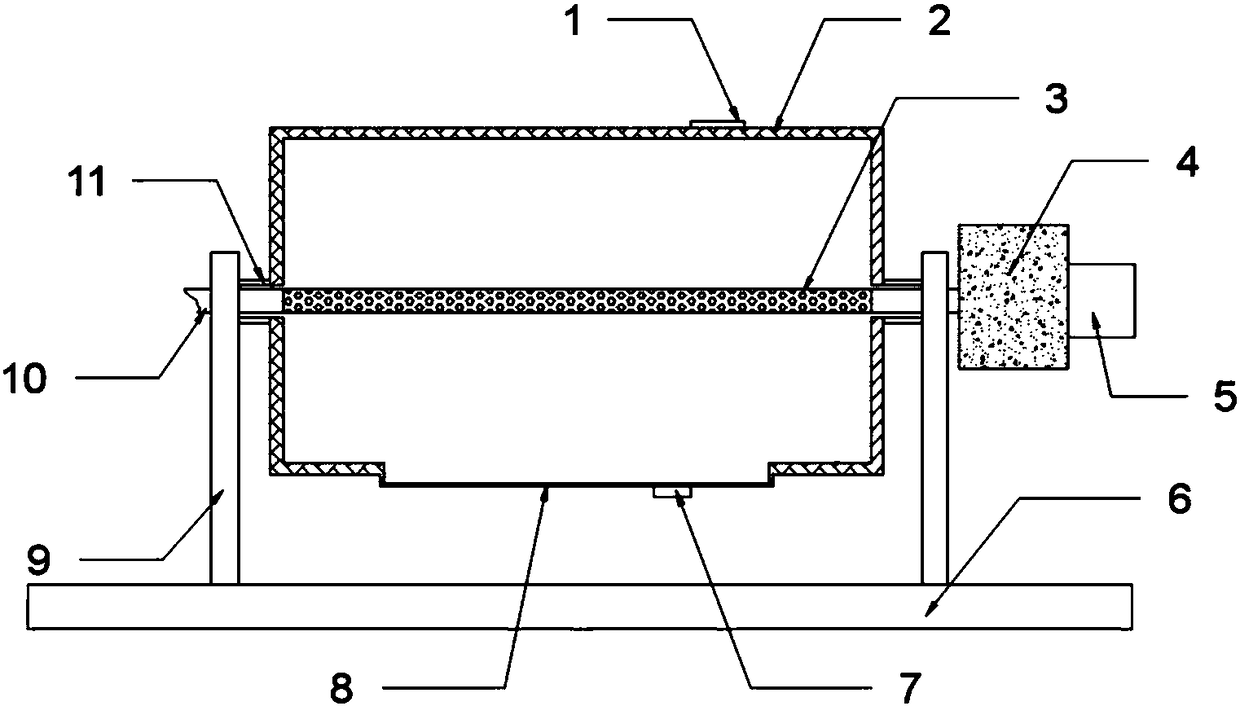
[0026] A negative pressure drum dryer includes a base 6, a bracket 9 mounted on the base, and a drying cylinder 1 that is rotatably matched with the bracket 9 through a shaft 11; the top of the drying cylinder 2 is provided with a feed hole 1, and A discharge port 8 is provided at the bottom; it is characterized in that: the shaft 7 is provided with a shaft hole; a heating layer is integrated in the wall of the drying cylinder 2; a hollow structure is installed in the cylinder cavity of the drying cylinder 2 Ventilation tube 10; the two ends of the ventilation tube 2 extend out of the shaft hole and pass through the bracket; the ventilation tube 3 is located on the tube wall inside the drying cylinder 3 with ventilation holes 3.

Embodiment 2

[0028] Based on Example 1, in order to improve the moisture absorption efficiency of the air flowing through the ventilation pipe, the following improvements are made: a drying device is provided at one end of the ventilation pipe 10; the drying device includes a drying box 4 and an inlet set on the drying box 4 Tuyere 5; The inside of the drying box 4 is filled with desiccant.

[0029] Through the action of the drying device, the humidity of the air flowing through the inside of the ventilation pipe is reduced, and the humidity difference between the inside of the ventilation pipe and the inside of the drying cylinder is enlarged. Driven by the physical action of the humidity difference, the moisture in the drying cylinder can more easily escape into the ventilation pipe through the ventilation holes and be taken out, which further reduces the humidity in the drying cylinder and reduces the moisture regain of grain particles in the subsequent cooling step.

Embodiment 3

[0031] Based on Example 1, in order to reduce the influence of the resistance of the drying box on the speed of air flowing into the ventilation pipe, the following improvement is made: the diameter of the air inlet 5 is larger than the diameter of the ventilation pipe 10.

[0032] Through the design of the air inlet size, the drying box is equipped with the function of a booster device. The colleagues who counteract its resistance can maintain or increase the flow rate of the air after passing through the drying box, thereby ensuring the negative pressure effect generated by the ventilation pipe.


PUM


Abstract

The invention relates to a negative pressure type roller dryer. The negative pressure type roller dryer comprises a base, supports and a drying barrel; the supports are arranged on the base; the drying barrel is in rotation fit with the supports through shaft rods; a feeding hole is formed in the top of the drying barrel; a discharge port is formed in the bottom of the drying barrel; shaft holes are formed in the shaft rods; a heating layer is integrated in the barrel wall of the drying barrel; a ventilating pipe with a hollow structure is arranged in a barrel cavity of the drying barrel; thetwo ends of the ventilating pipe stretch out of the shaft holes and penetrate out of the supports; and ventilating holes are formed in the parts, located in the drying barrel, of the pipe wall of theventilating pipe. The humidity and the pressure in the drying barrel can be effectively reduced, and discharge of moisture in grains is accelerated; the moisture of air in the drying barrel can be pumped, so that the situation that the grains absorb water and are wetted back in the cooling process is avoided; the grains in the drying barrel can be subjected to sampling analysis, so that a destination of drying operation is accurately grasped; and the final drying quality of the grains is ensured.

Description

Technical field [0001] The invention relates to the field of grain drying equipment, in particular to a negative pressure drum dryer. Background technique [0002] Food is the heaven for the people, and food as the foundation of the people's life and safety has always been one of the country's important strategic war preparations. Since the traditionally dried grain still contains a lot of water, it will usually mold or sprout after being stored for less than 1 year. The above-mentioned is even shorter in the years when the rainy weather is more frequent. If there is a continuous climate abnormality, the grain production will be reduced, and the grain storage will also shrink significantly. This is obviously not in line with the positioning of the strategic preparation materials for grain. Therefore, at present, drying is used instead of drying to further reduce the moisture content of grains, thereby further extending the storage time of grains to meet the needs of strategic wa...

Claims


Application Information

Patent Timeline
Patent Type & Authority Applications(China)
IPC IPC(8): F26B11/04F26B25/16F26B21/00F26B21/08F26B23/06F26B23/08A23B9/08
CPCF26B11/04A23B9/08F26B3/347F26B11/0495F26B21/004F26B21/083F26B23/06F26B25/16F26B2200/06
Inventor 王波
Owner 郑州龙威电气安装有限公司
Why Eureka
Try Eureka