
A mechanical variable valve mechanism

A valve train, mechanical technology, applied in mechanical equipment, machine/engine, engine components, etc., can solve problems such as increased engine cost, large impact force, complex system, etc., to achieve the effect of simple control and reduction of lateral force

Active Publication Date: 2019-06-04
CHINA NORTH ENGINE INST TIANJIN
View PDF5 Cites 0 Cited by
  • Summary
  • Abstract
  • Description
  • Claims
  • Application Information

AI Technical Summary

Problems solved by technology

Compared with the disadvantages of high energy consumption of electromagnetic drive, low and unstable response speed of electric drive, and complex motor-driven system, the camless gas distribution technology of electro-hydraulic drive has relatively simple structure and fast response speed
However, it also has unavoidable disadvantages: the flow rate of the hydraulic system is not enough at high speed, the valve reaches the maximum lift and the seat is fast, and the impact force is large.
Therefore, it is mainly used in low-speed engines such as diesel engines. In addition, it is necessary to use expensive electro-hydraulic servo systems and relatively complex control technologies to accurately control the valve stroke to avoid seating impact, which greatly increases the engine. cost

Method used


Image

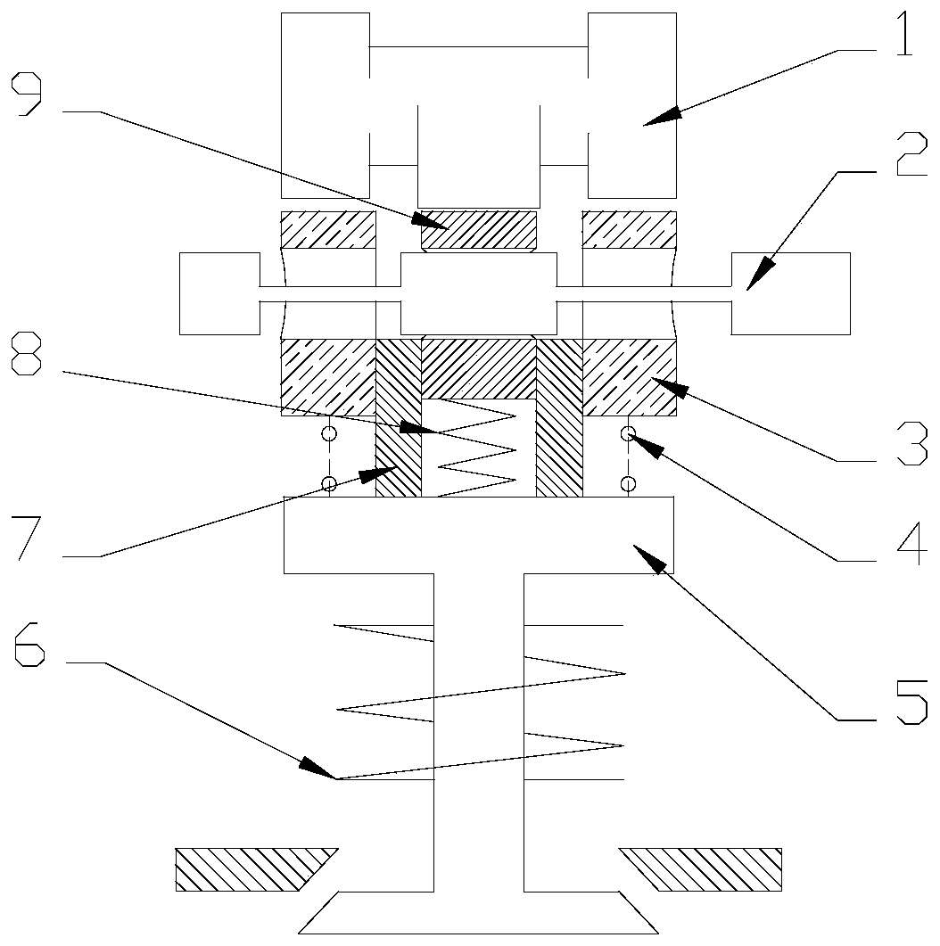
  • A mechanical variable valve mechanism
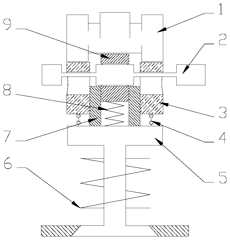
  • A mechanical variable valve mechanism
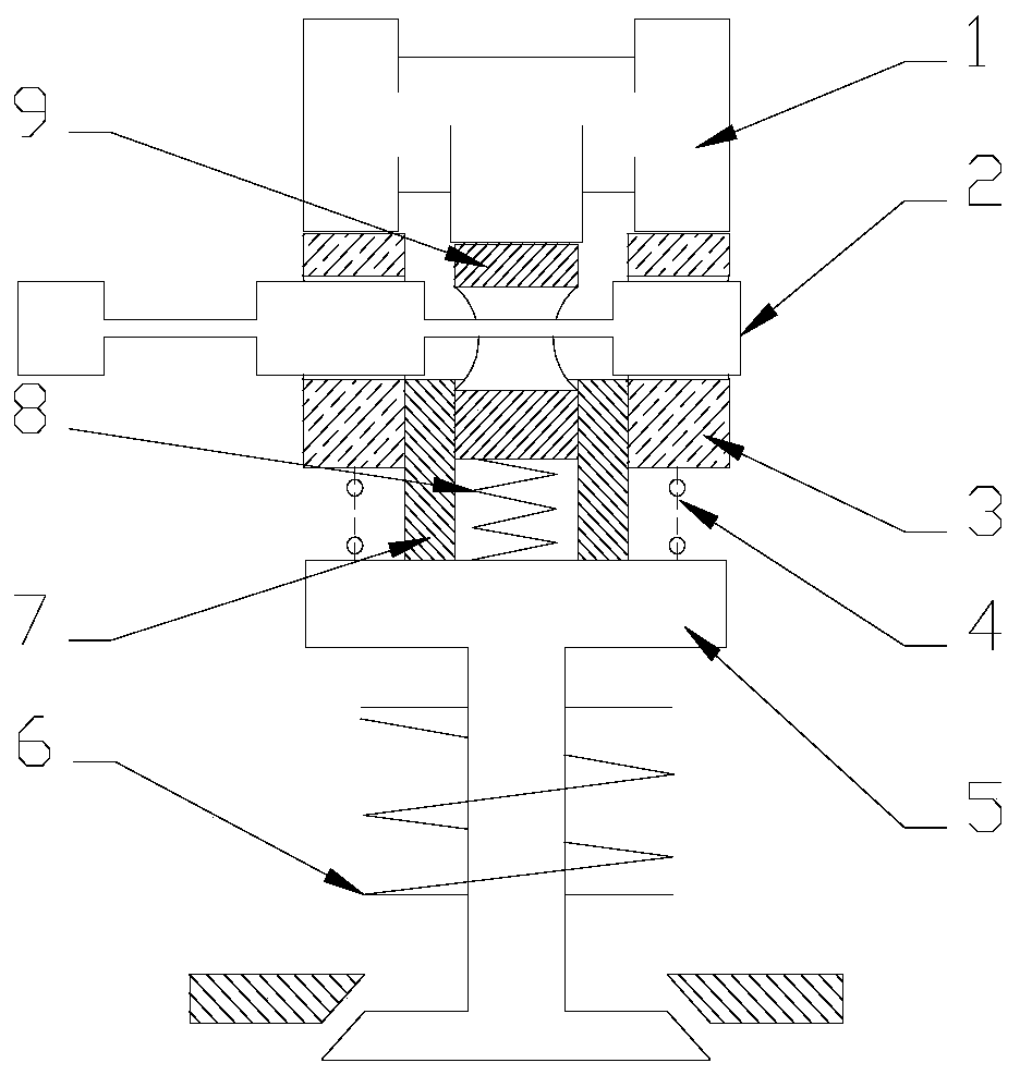
  • A mechanical variable valve mechanism

Examples


Embodiment Construction

[0037] It should be noted that, in the case of no conflict, the embodiments of the present invention and the features in the embodiments can be combined with each other.

[0038] In describing the present invention, it should be understood that the terms "center", "longitudinal", "transverse", "upper", "lower", "front", "rear", "left", "right", " The orientations or positional relationships indicated by "vertical", "horizontal", "top", "bottom", "inner" and "outer" are based on the orientations or positional relationships shown in the drawings, and are only for the convenience of describing the present invention and Simplified descriptions, rather than indicating or implying that the device or element referred to must have a particular orientation, be constructed and operate in a particular orientation, and thus should not be construed as limiting the invention. In addition, the terms "first", "second", etc. are used for descriptive purposes only, and should not be understood ...


PUM


Abstract

The invention provides a mechanical variable valve mechanism. The mechanical variable valve mechanism comprises a cam, a bushing and a plunger. The bottom of the cam is matched with the top of the plunger and the top of the bushing. The plunger and a plunger bushing are sequentially sleeved with the bushing from inside to outside. The surface of the plunger bushing can slide relative to the plunger and the bushing. The upper surface of the plunger bushing is connected with a control lever in a contact mode. The control lever is matched with a through hole in the middle of the bushing and a through hole in the middle of the plunger. The bottom of the plunger bushing is connected to a valve. A bushing spring is arranged between the top of the valve and the bushing. A plunger spring is arranged between the top of the valve and the plunger. A valve spring is arranged in the valve. According to the mechanical variable valve mechanism, by changing horizontal movement of the control lever, the matching rule between a boss of the control level and the through holes in the middle of the bushing and in the middle of the plunger can be changed, the movement rule of the valve is changed finally, and the stoke can be changed by one half.

Description

technical field [0001] The invention belongs to the field of engines, in particular to a mechanical variable valve mechanism. Background technique [0002] The internal combustion engine is still the prime mover with the highest thermal efficiency and the largest power per unit volume and unit weight. It is widely used. However, with the gradual shortage of energy in the world and the continuous deterioration of environmental resources, we need internal combustion engines to meet stricter emission regulations and economic indicators. . Traditional internal combustion engines use fixed-profile camshafts to drive valves, which makes the emissions and fuel consumption of internal combustion engines not optimal at all operating points. Therefore, most new internal combustion engines use variable valve technology to control emissions and reduce fuel consumption. [0003] At present, variable valve technology is mainly divided into camshaft-based variable gas distribution technol...

Claims


Application Information

Patent Timeline
Patent Type & Authority Patents(China)
IPC IPC(8): F01L13/00F01L1/04
CPCF01L1/04F01L13/00
Inventor 张翔宇杨震寰黄树和李研芳刘胜梁红波
Owner CHINA NORTH ENGINE INST TIANJIN
Learn More