
Cutter grinding machine

A knife sharpening machine and sharpening stone technology, applied in the direction of grinding workpiece supports, other manufacturing equipment/tools, manufacturing tools, etc., can solve the problems of manual hand-held kitchen knives, unsatisfactory effect, operator injury, etc. It is easy to observe the sharpening state and improve the safety effect.

Inactive Publication Date: 2018-08-17
CHANGZHOU COLLEGE OF INFORMATION TECH
View PDF0 Cites 5 Cited by
  • Summary
  • Abstract
  • Description
  • Claims
  • Application Information

AI Technical Summary

Problems solved by technology

Because kitchen knives are used frequently and need to be sharpened frequently, how to sharpen the knife is a headache for many people, and knife sharpeners cannot be found at any time. The whetstone is time-consuming and laborious to grind, and the effect is not ideal.
At present, most of the popular electric knife sharpening components on the market are directly driven by the motor to grind the grinding wheel. When grinding, it is necessary to manually hold the kitchen knife. Because the motor rotates at a high speed, it is very unsafe and often causes harm to the operator.

Method used


Image

  • Cutter grinding machine
  • Cutter grinding machine
  • Cutter grinding machine

Examples


Embodiment 1

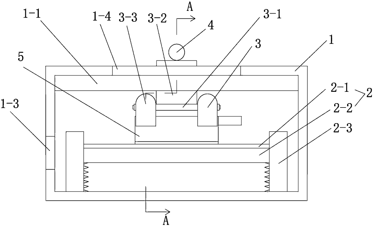
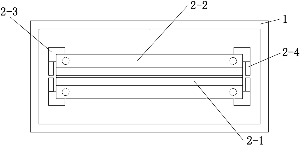
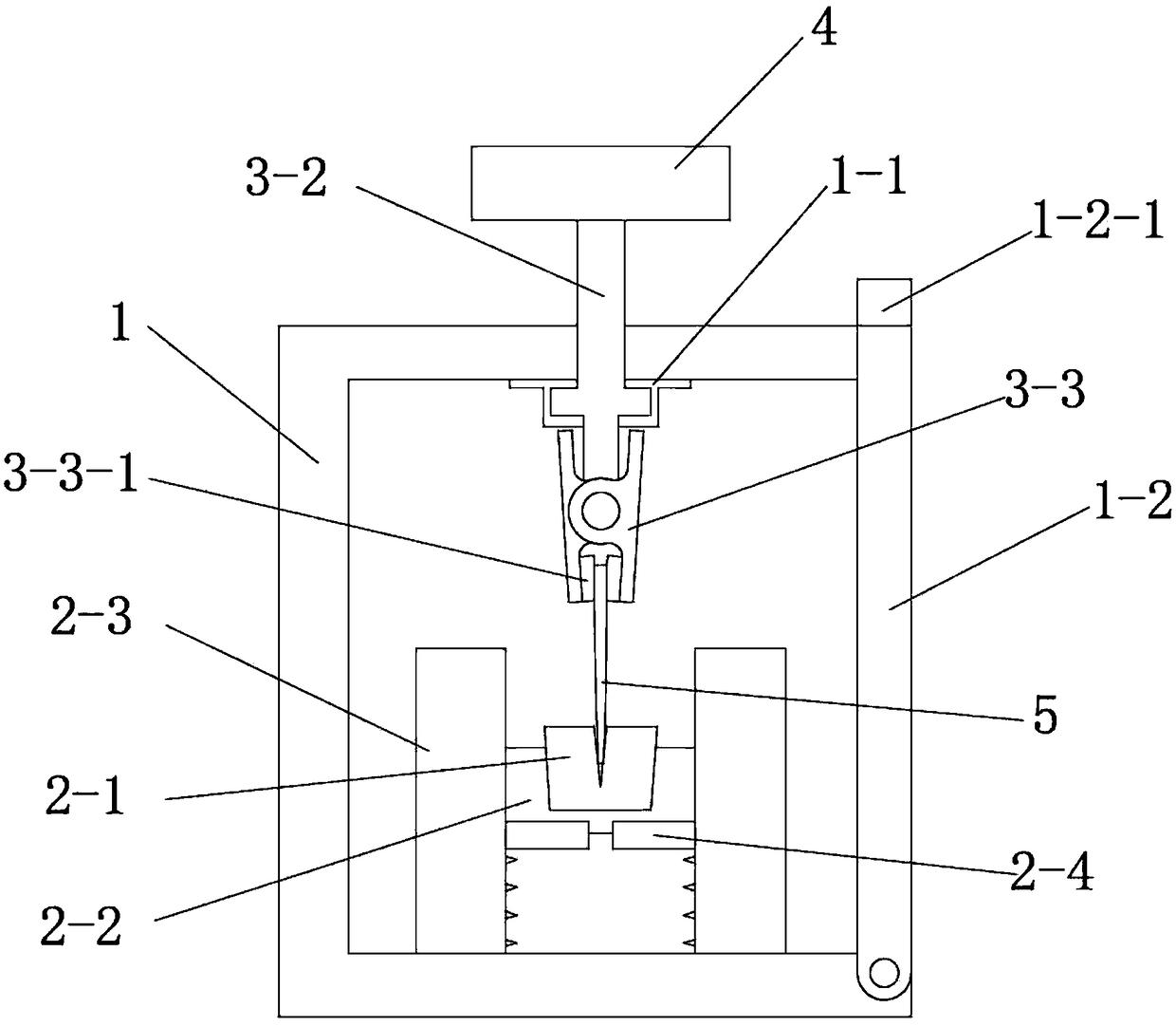
[0051] See Figure 1 to Figure 4 , The knife sharpener of this embodiment includes a chassis 1, a knife sharpening assembly 2, a clamping device 3 and a handle 4. One side of the case 1 is open, and a protective cover 1-2 is rotatably connected. The bottom of the protective cover 1-2 is rotatably connected with the bottom of the open side of the cabinet 1. The inner top of the protective cover 1-2 is provided with an iron plate. The top of the open side of the cabinet 1 is provided with a magnet corresponding to the position of the iron sheet on the protective cover 1-2. In order to open or close the protective cover 1-2 conveniently, a handle 1-2-1 is provided on the top of the protective cover 1-2. The knife sharpening assembly 2 and the clamping device 3 are slidably arranged on the top of the cabinet 1 and directly above the knife sharpening assembly 2 . The sliding direction of the clamping device 3 is consistent with the length direction of the sharpening assembly 2 ...

Embodiment 2

[0056] See Figure 5 , This embodiment is basically the same as Embodiment 1, except that the cross section of the guide post 2-3 is W-shaped. Compared with Embodiment 1, this embodiment adds two sliding surfaces, so that the sliding of the whetstone mounting base 2-2 is more stable.

[0057] The working principle of this embodiment: the present invention realizes the continuous grinding of the kitchen knife through the V-shaped groove on the whetstone and the spring between the bottom of the whetstone mounting seat 2-2 and the bottom of the cabinet 1, and the cutting edge Gradually thinning, the spring slowly bounces the whetstone 2-1, so that the cutting edge of the kitchen knife can be sharpened more and more sharply. First, press the whetstone mounting seat 2-2 until the spring is compressed to the maximum state, turn the limit stop 2-4 to the top of the whetstone mounting seat, release your hand, and under the action of the spring, the limit stop 2 -4 Restrict the upwar...

Embodiment 3

[0059] See Figure 6 , This embodiment is basically the same as Embodiment 1, except that the handle 1-2-1 is replaced by a handle groove 1-2-2 arranged on the top of the front end of the protective cover 1-2.


PUM


Abstract

The invention discloses a cutter grinding machine comprising a case, a cutter grinding assembly, a clamping device and a handle. The cutter grinding assembly is arranged in the case in an up-down slidable mode, and springs are arranged between the cutter grinding assembly and the bottom of the case; the clamping device is slidably arranged at the top of the case and located over the cutter grinding assembly; the sliding direction of the clamping device is consistent with the length direction of the cutter grinding assembly; the clamping device is used for clamping a cutter placed on the cuttergrinding assembly; and the handle is fixed to the top of the clamping device. According to the cutter grinding machine, cutter grinding can be conducted at any time according to the requirement of auser, thus a large amount of waiting time is saved, using is not affected, and cutter grinding through a traditional grinding wheel is avoided, so that safety is improved.

Description

technical field [0001] The invention relates to a sharpener. Background technique [0002] The kitchen knives in the kitchen will become dull after being used for a period of time, especially when chopping relatively hard ingredients, such as chicken nuggets with bones. Because kitchen knives are used frequently and need to be sharpened frequently, how to sharpen the knife is a headache for many people, and knife sharpeners cannot be found at any time. The whetstone is also time-consuming and laborious to grind, and the effect is not ideal. Most of the popular electric knife sharpening components on the market are directly driven by the motor to grind the grinding wheel. When grinding, a kitchen knife needs to be manually held. Because the motor rotates at a high speed, it is very unsafe and often causes injury to the operator. Contents of the invention [0003] The purpose of the present invention is to provide a sharpening machine which is easy to use and has high safe...

Claims


Application Information

Patent Timeline
Patent Type & Authority Applications(China)
IPC IPC(8): B24B3/36B24B41/06
CPCB24B3/36B24B41/06
Inventor 刘海兰李小平
Owner CHANGZHOU COLLEGE OF INFORMATION TECH
Learn More