
Wire rod wire rolling line guide groove and method for preventing wire rod rolling line from being scratched

A technology of guide grooves and wire rods, applied in the field of steel rolling, can solve problems such as surface scratches, achieve the effects of improving the surface quality of finished products, reducing temperature, and saving manufacturing costs and spare parts costs

Active Publication Date: 2018-08-17
MAANSHAN IRON & STEEL CO LTD
View PDF17 Cites 1 Cited by
  • Summary
  • Abstract
  • Description
  • Claims
  • Application Information

AI Technical Summary

Problems solved by technology

It is used to solve the problem that in the prior art, in the process of wire rod rolling, the surface of the wire rod rolling product is easily scratched when it passes through the straight climbing section and the curve section

Method used


Image

  • Wire rod wire rolling line guide groove and method for preventing wire rod rolling line from being scratched
  • Wire rod wire rolling line guide groove and method for preventing wire rod rolling line from being scratched
  • Wire rod wire rolling line guide groove and method for preventing wire rod rolling line from being scratched

Examples


Embodiment Construction

[0028] In the present invention, it should be understood that the terms "length", "width", "upper", "lower", "front", "rear", "left", "right", "vertical", "horizontal" ", "Top", "Bottom", "Inner", "Outer", "Clockwise", "Counterclockwise", "Axial", "Radial", "Circumferential" and other indications are based on The orientation or positional relationship shown in the drawings is only for the convenience of describing the present invention and simplifying the description, and does not indicate or imply that the referred device or element must have a specific orientation, be constructed and operated in a specific orientation, and therefore cannot be understood as Limitations on the Invention.

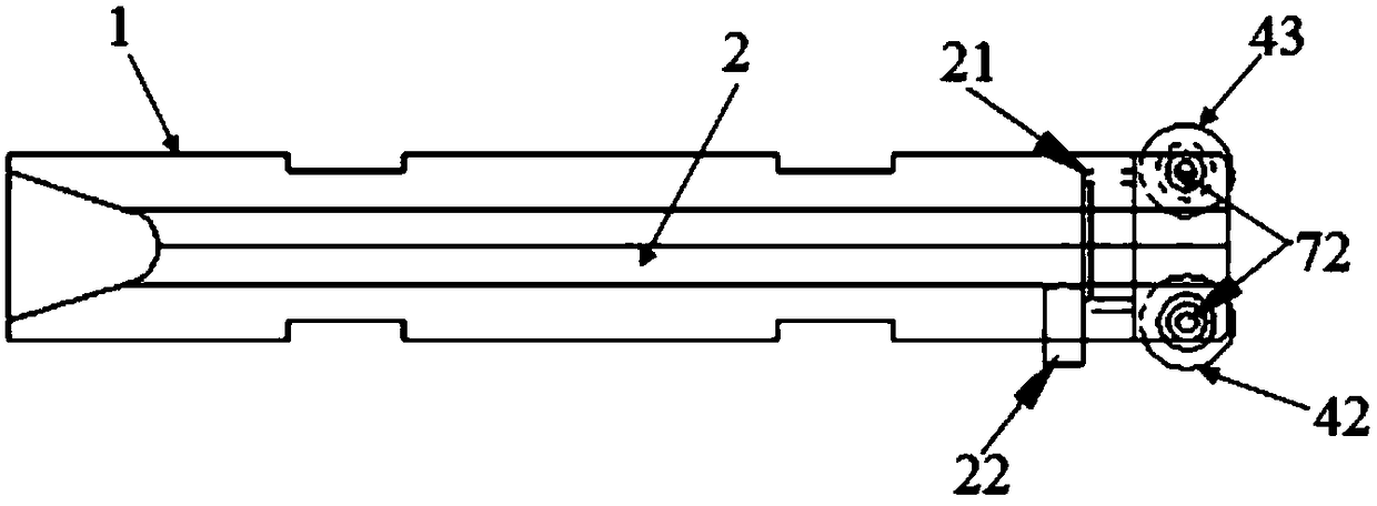
[0029] Such as figure 1 , figure 2 , image 3 , Figure 4 , Figure 5 As shown, a wire rolling guide groove includes a guide groove base 1, a guide groove 2 is provided inside the guide groove base 1 for the wire rod rolling piece 5 to pass through, and the guide groove base 1 is also ...


PUM


Abstract

The invention discloses a wire rod rolling line guide groove and a method for preventing a wire rod rolling line from being scratched. The wire rod rolling line guide groove comprises a guide groove base, wherein a guide groove allowing a wire rod rolled piece to pass through is formed in the guide groove base, and a guide roller assembly capable of freely rotating is arranged at one end of the guide groove base; and the guide roller assembly comprises a first guide roller, a second guide roller and a third guide roller, the first guide roller is connected to a guide groove cover plate througha support, the second guide roller and the third guide roller are symmetrically arranged on the guide groove base, and one end of the guide groove can freely rotate along the guide groove base. The guide groove is of a U-shaped groove structure, a guide rail formed by the corresponding second guide roller and the third guide roller is of a U-shaped groove structure, and the first guide roller isarranged at the open end of the guide rail U-shaped structure. The wire rod rolling line guide groove is installed at a climbing position of a rolling line straight line section, so that the traditional friction form between the four sides of the wire rod rolled piece at the climbing position and the guide groove is changed, the sliding friction is changed into rolling friction, the mechanical scratching of the wire rod rolled piece in the rolling process is reduced, and the surface quality of finished products is improved.

Description

technical field [0001] The invention belongs to the technical field of steel rolling, and in particular relates to a wire rolling guide groove and a method for preventing wire binding and scratching. Background technique [0002] At present, the guide grooves used in the high-speed wire rolling lines of most steel mills are commonly used sliding guide grooves. This kind of sliding guide grooves can basically meet the needs of construction wire rods, but cannot meet the needs of high value-added special steel. The technical level and usage requirements on the slope. Especially for cold heading steel, spring steel, cord steel and other wire products with high surface quality requirements, the use of commonly used sliding guide grooves on curves and climbing slopes has been unable to meet customers' requirements for cold heading steel and subsequent wire rolling. process requirements. [0003] According to research, when there are pits greater than 0.03mm deep on the surface ...

Claims


Application Information

Patent Timeline
Patent Type & Authority Applications(China)
IPC IPC(8): B21B39/14
CPCB21B39/14
Inventor 宫辉彭进明孙凯葛晴晴
Owner MAANSHAN IRON & STEEL CO LTD
Learn More