
A multi-stage air-cooled heat dissipation device

A heat dissipation device and multi-stage wind technology, which is applied in cooling/ventilation/heating transformation, semiconductor/solid-state device parts, semiconductor devices, etc., can solve the problem of single heat dissipation effect, increase enterprise income, improve product yield, The effect of extending the service life cycle

Active Publication Date: 2020-02-21
广西自贸区见炬科技有限公司 +1
View PDF11 Cites 0 Cited by
  • Summary
  • Abstract
  • Description
  • Claims
  • Application Information

AI Technical Summary

Problems solved by technology

The heat dissipation effect of this structure is relatively simple, which cannot meet the current needs of saving resources and eliminating noise.

Method used


Image

  • A multi-stage air-cooled heat dissipation device
  • A multi-stage air-cooled heat dissipation device
  • A multi-stage air-cooled heat dissipation device

Examples


Embodiment 1

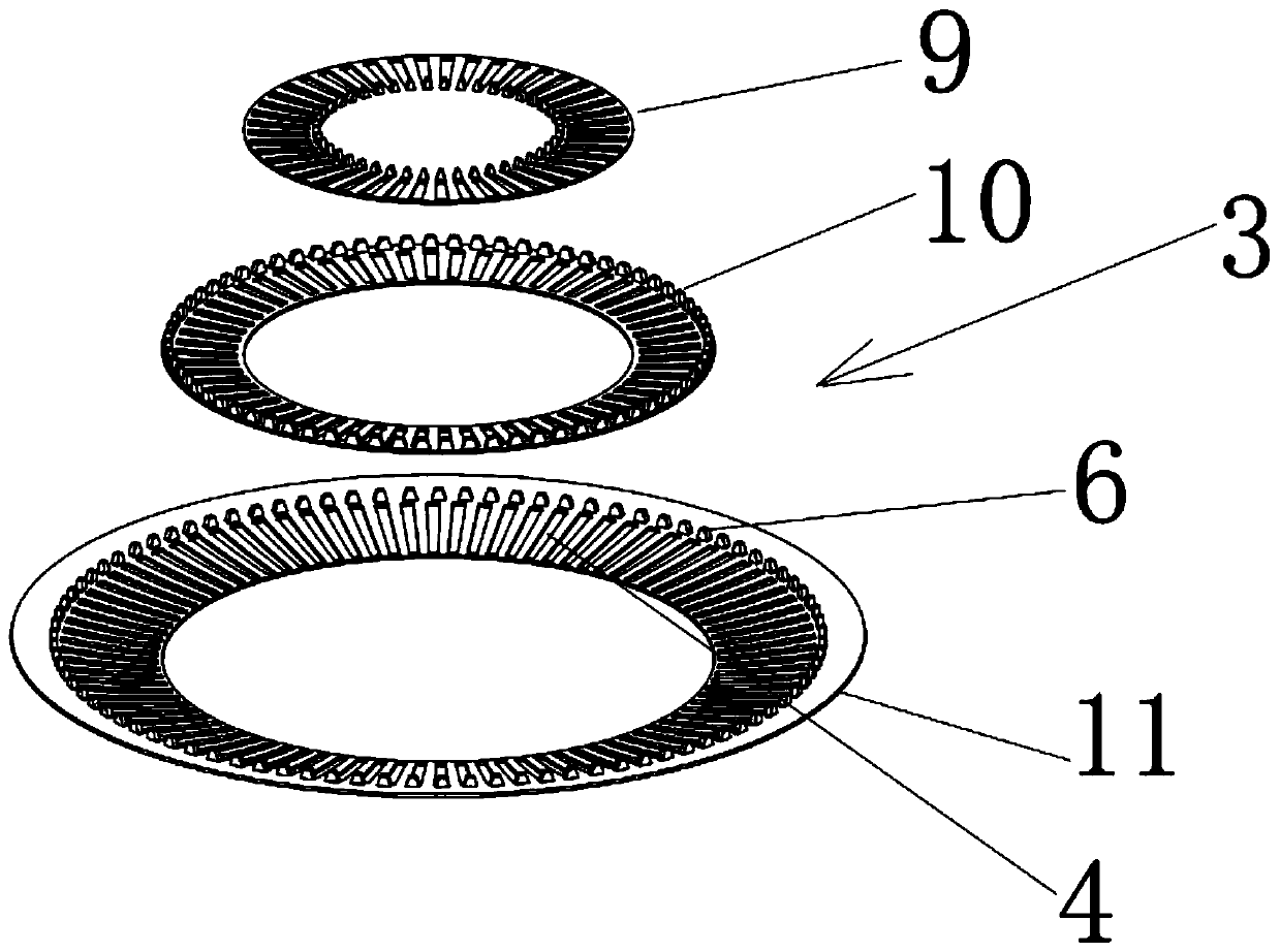
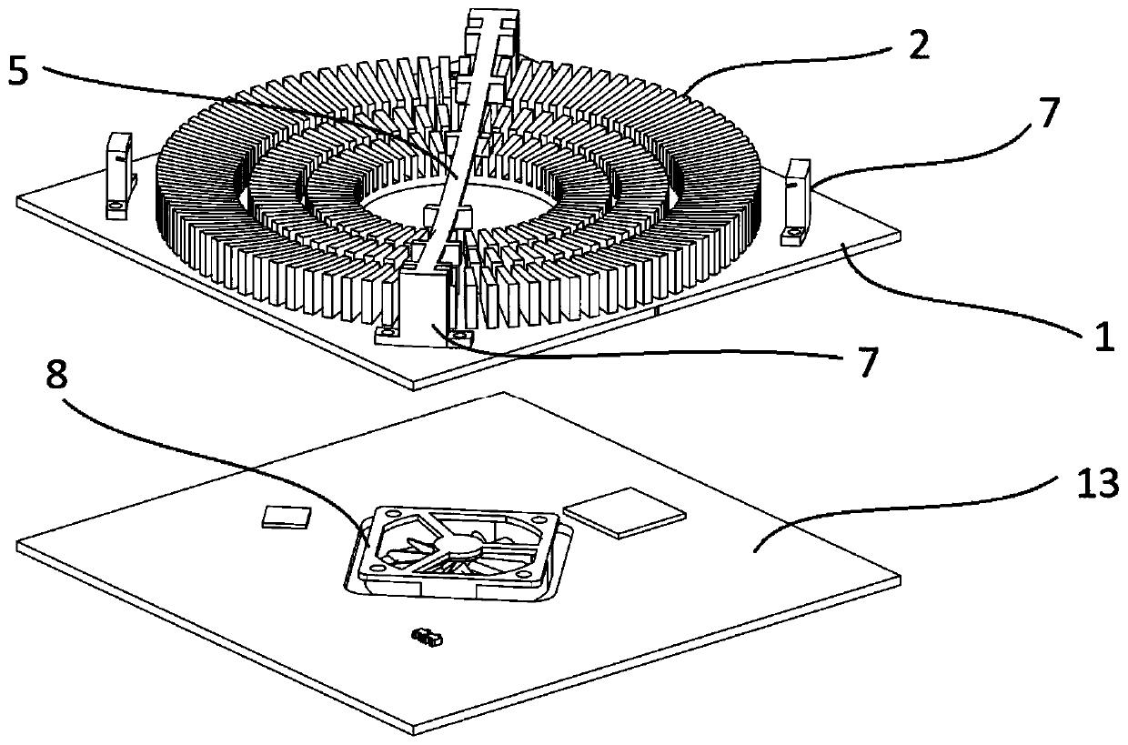
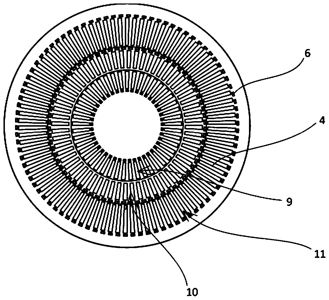
[0045] A multi-stage air-cooled heat sink, such as Figure 1-4 As shown, it is used for the heat dissipation of the PCB board. Specifically, a heat sink 1 is arranged on the PCB board, and the PCB board mainly performs heat dissipation through the heat sink 1. The present invention achieves the heat dissipation of the PCB board by controlling the heat dissipation of the heat sink 1. control.

[0046] Regarding the key components of the present invention, namely the heat sink 1 and other components loaded on the heat sink 1 .

[0047] Specifically, it includes a number of fins 2 arranged on the heat sink 1, and the fins 2 are arranged according to a certain rule. The inner diameters of the arrangement groups formed by the fins 2 are different, forming a multi-layer structure from the inside to the outside.

[0048] The fins 2 arranged in multiple layers form multiple regions to a certain extent, and the boundaries of the regions are formed between layers, and then different hea...


PUM


Abstract

The invention relates to the technical field of heat radiation, and particularly to a multilevel air-cooled heat radiation device. The multilevel air-cooled heat radiation device comprises fins arranged on cooling fins; the fins are in multilayer annular arrangement; annular cooling plates different in size are arranged above the fins; and the cooling plates are embedded sequentially from big to small and from outside to inside. The heat radiation device is compact in structure, can save space occupied by a heat radiation system, not only can prolong the service life of a heating body, but also further can make the life be safe and at ease.

Description

technical field [0001] The invention relates to the technical field of heat dissipation, in particular to a multi-stage air-cooled heat dissipation device. It is mainly suitable for products in the electronic industry such as routers, computers, TV set-top boxes, audio and smart furniture that require rapid heat dissipation. Background technique [0002] With the development of electronic design and manufacturing technology, electronics and related industries pursue miniaturization, integration, high frequency and high computing speed, and the power density per unit area or volume of electronic components and equipment is getting higher and higher. Statistics show that since 1970, the density and performance of semiconductor transistors have increased rapidly, doubling almost every few months, and basically developing according to the predicted trend of the law. Electronic components are developing in the direction of light, thin, short, small, high performance, and multi-p...

Claims


Application Information

Patent Timeline
Patent Type & Authority Patents(China)
IPC IPC(8): H05K7/20H01L23/467
CPCH01L23/467H05K7/20136H05K7/20409
Inventor 吴明玉
Owner 广西自贸区见炬科技有限公司
Learn More