
Energy dissipation construction structure suitable for diffusion type drainage outlet

A diffused, outfall technology, applied in water conservancy projects, marine engineering, coastline protection, etc., can solve the problems of reduced energy dissipation effect, less than uniform diffusion, seabed scour damage, etc., to achieve the effect of protecting safety and reducing scour damage

Pending Publication Date: 2018-08-14
TIANJIN RES INST FOR WATER TRANSPORT ENG M O T
View PDF7 Cites 6 Cited by
  • Summary
  • Abstract
  • Description
  • Claims
  • Application Information

AI Technical Summary

Problems solved by technology

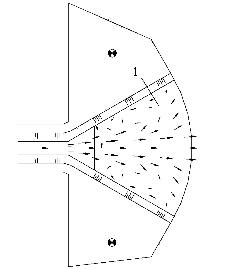
However, this structure is not effective, because when the diffusion angle is large, the water flow will not spread evenly along the diffusion angle, but after entering the diffusion stilling pool, it will rush straight to the downstream along the outflow direction. There is no time for uniform diffusion, and the middle part of the diffusion stilling basin is an obvious mainstream area. At the same time, the basic flow state between the left and right recirculation areas and the main flow area is formed between the wing walls on both sides of the outlet, which greatly reduces the energy dissipation effect and causes seabed scour. Serious damage, affecting the safety of the outfall structures

Method used


Image

  • Energy dissipation construction structure suitable for diffusion type drainage outlet
  • Energy dissipation construction structure suitable for diffusion type drainage outlet
  • Energy dissipation construction structure suitable for diffusion type drainage outlet

Examples


Embodiment Construction

[0014] In order to further understand the invention content, characteristics and effects of the present invention, the following examples are given, and detailed descriptions are as follows in conjunction with the accompanying drawings:

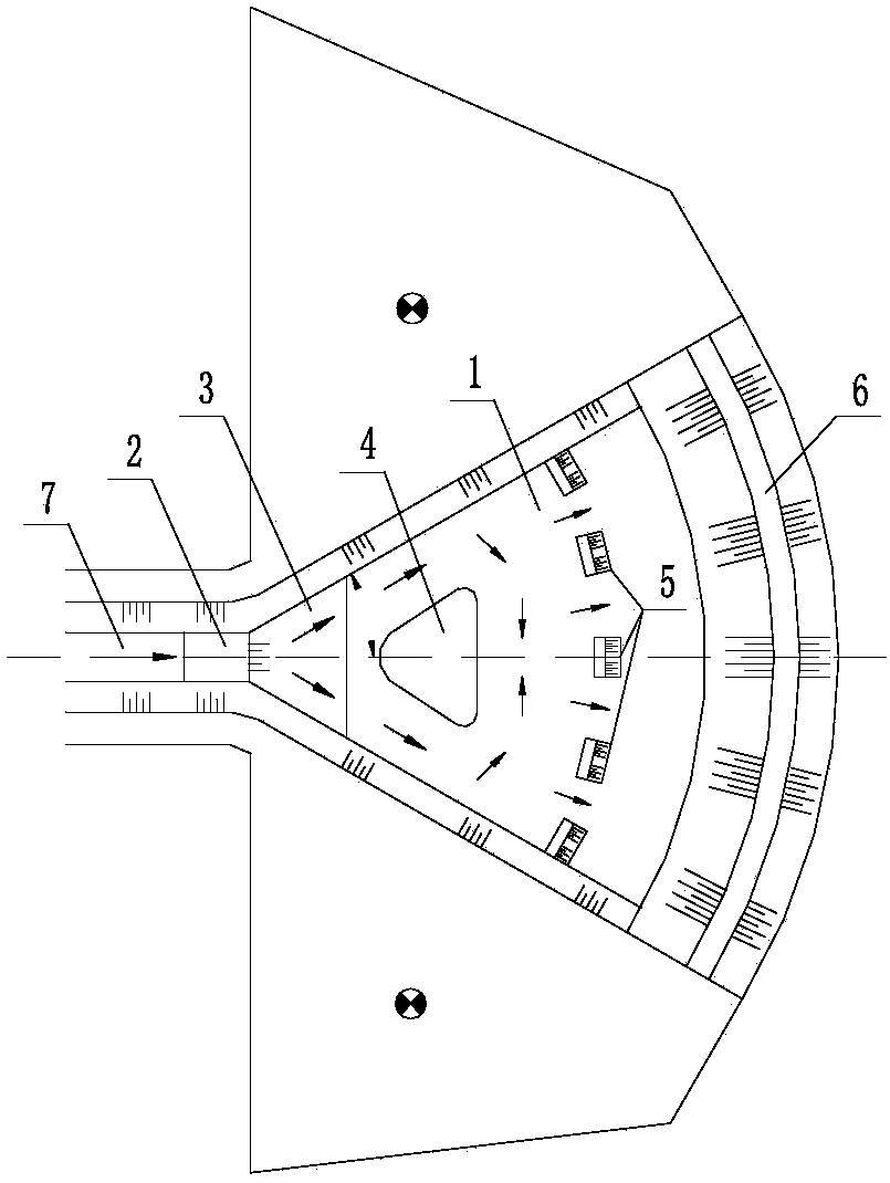
[0015] see figure 2 with image 3 , an energy dissipation structure suitable for diffused outfalls, including a diffused stilling basin 1, the structure also includes a flat slope section arranged at the end of the upstream open drainage channel 7, and the flat slope section 2 of the upstream open drainage channel passes through the slope 3 and The diffusion stilling pool 1 is connected, and the slope 3 is arranged in the diffusion stilling pool 1; in the diffusion stilling pool 1, a flow diversion pier 4 and a plurality of Stilling pier 5; the cross-section of the diversion pier 4 is an isosceles triangle arranged symmetrically along the center line of the plane of the diffusion stilling pool, and the apex of the isosceles triangle is oppo...


PUM


Abstract

The invention discloses an energy dissipation construction structure suitable for a diffusion type drainage outlet. The energy dissipation construction structure suitable for the diffusion type drainage outlet comprises a diffusion type stilling pool, and also comprises a flat slope section arranged at the tail end of an upstream drainage open channel, and the flat slope section of the upstream drainage open channel is connected with the diffusion type stilling pool through a slope. The diffusion type stilling pool is internally provided with a diversion pier and a plurality of stilling piersin sequence in the flow-out direction. The cross section of the diversion pier is an isosceles triangle which is symmetrically arranged along a center line of the plane of the diffusion type stillingpool, and the apical angle of the isosceles triangle is opposite to the flat slope section of the upstream drainage open channel. A row of arc pier gates arching upstream are formed by the multiple stilling piers. The top elevations of the diversion pier and the stilling piers are higher than the water level of the diffusion type stilling pool. The tail end of the diffusion type stilling pool is aslope type tail ridge which is in an arc shape, and the top elevation of the slope type tail ridge is higher than the bottom elevation of the flat slope section of the upstream drainage open channel.The energy dissipation construction structure suitable for the diffusion type drainage outlet can fully diffuse the water flow, greatly improves the energy dissipation effect, and slows down the erosion damage to a seabed caused by drainage.

Description

technical field [0001] The invention belongs to the field of electric power engineering hydraulic structures, and in particular relates to an energy dissipation structure suitable for a diffused drain. Background technique [0002] A power plant uses seawater as a cooling water source and discharges it into the sea through the outlet. Since the discharged water has a large kinetic energy, continuous discharge will scour the seabed near the outlet, thereby affecting the stability of the outlet structure. Therefore, it is necessary to Take corresponding energy dissipation and anti-shock measures. The common energy dissipation structure of the outfall is the diffusion stilling basin 1, please refer to figure 1 , the discharged water flows into the sea after passing through diffusion energy dissipation. However, this structure is not effective, because when the diffusion angle is large, the water flow will not spread evenly along the diffusion angle, but after entering the dif...

Claims


Application Information

Patent Timeline
Patent Type & Authority Applications(China)
IPC IPC(8): E02B8/06
CPCE02B8/06
Inventor 李焱肖辉陈汉宝刘海源耿宝磊戈龙仔刘海成张慈珩刘针管宁谭忠华胡克彭程马隽张维熊岩
Owner TIANJIN RES INST FOR WATER TRANSPORT ENG M O T
Learn More