
Pneumatic spot welding machine

A pneumatic spot welding machine technology, applied in welding equipment, resistance welding equipment, metal processing equipment and other directions, can solve the problems of poor heat dissipation performance of the chassis, poor fixed protection function, etc., and achieves a simple structure, improved protection function, and convenient operation. Effect

Inactive Publication Date: 2018-08-14
安徽雄风防护设施有限公司
View PDF8 Cites 3 Cited by
  • Summary
  • Abstract
  • Description
  • Claims
  • Application Information

AI Technical Summary

Problems solved by technology

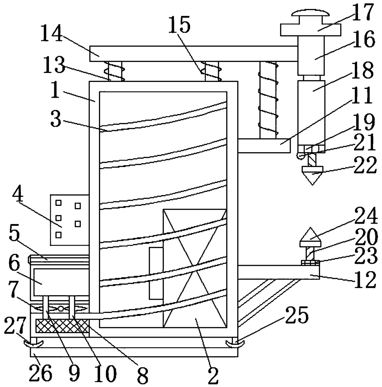
[0005] The purpose of the present invention is to solve the problem of poor fixed protection function of welded parts with low hardness and poor heat dissipation performance of the chassis in the prior art, and proposes a pneumatic spot welder

Method used

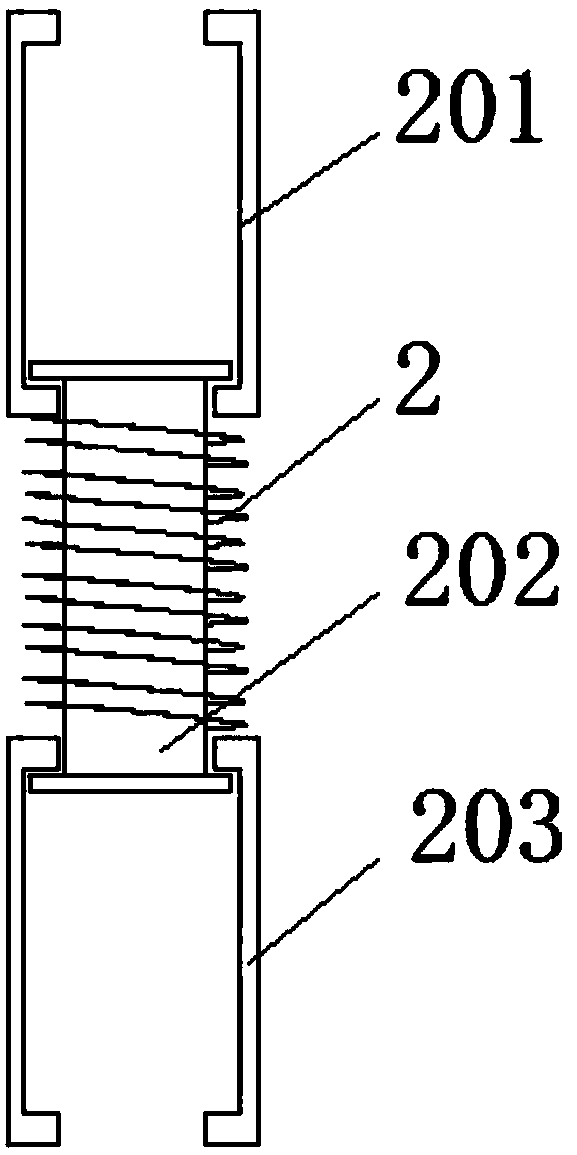
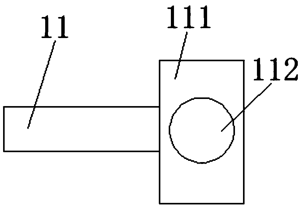

Image

  • Pneumatic spot welding machine
  • Pneumatic spot welding machine
  • Pneumatic spot welding machine

Examples


Embodiment Construction

[0022] The following will clearly and completely describe the technical solutions in the embodiments of the present invention with reference to the accompanying drawings in the embodiments of the present invention. Obviously, the described embodiments are only some, not all, embodiments of the present invention.

[0023] In describing the present invention, it should be understood that the terms "upper", "lower", "front", "rear", "left", "right", "top", "bottom", "inner", " The orientation or positional relationship indicated by "outside", etc. is based on the orientation or positional relationship shown in the drawings, and is only for the convenience of describing the present invention and simplifying the description, rather than indicating or implying that the referred device or element must have a specific orientation, so as to Specific orientation configurations and operations, therefore, are not to be construed as limitations on the invention.

[0024] refer to Figure ...


PUM


Abstract

The invention discloses a pneumatic spot welding machine. The pneumatic spot welding machine comprises an electric welding machine box, wherein an inner cavity of the electric welding machine box is hollow, a transformer is fixedly connected to the inner side wall of one side of the electric welding machine box, a heat dissipation tube which is spirally distributed is fixedly arranged on the innerside wall of the electric welding machine box, an electric control box, a water pump, a liquid cooling head filled with cooling liquid, a heat dissipation fan and a liquid cooling gate are sequentially connected to the outer side wall of one side of the electric welding machine box in the vertical direction, the end portion of the heat dissipation tube penetrates through the inner side wall of the electric welding machine box and communicates with the liquid cooling gate, the top of the liquid cooling gate is in contact connection with the heat dissipation fan, a liquid inlet pipe and a liquid outlet pipe are connected between the liquid cooling gate and the liquid cooling head, and the outer side wall of one side, far away from the electric control box, of the electric welding machine box is sequentially connected with an upper electrode arm and a lower electrode arm which are transversely placed in the vertical direction. The pneumatic spot welding machine is simple in structure, convenient to operate and capable of carrying out buffering and pressure monitoring when a welding part is tightly pressed; and the protection function to the welding part is improved, and meanwhile, the heat dissipation performance of the spot welding machine is improved, and the working stability is guaranteed.

Description

technical field [0001] The invention relates to the technical field of spot welding equipment, in particular to a pneumatic spot welding machine. Background technique [0002] The spot welding machine adopts the principle of double-sided double-point overcurrent welding. When working, two electrodes pressurize the workpiece so that the two layers of metal form a certain contact resistance under the pressure of the two electrodes, and the welding current flows from one electrode to the other. Instantaneous thermal fusion is formed at the two contact resistance points, and the welding current flows from the other electrode along the two workpieces to this electrode to form a loop, and will not damage the internal structure of the workpiece to be welded. According to the purpose of spot welding, there are universal type and special type; according to the number of welding points welded at the same time, there are single-point, double-point, and multi-point; according to the con...

Claims


Application Information

Patent Timeline
IPC IPC(8): B23K11/11B23K11/36
CPCB23K11/115B23K11/36
Inventor 查何南熊集泉毕达熊根兰
Owner 安徽雄风防护设施有限公司
Learn More