
Adhesive tape scrap edge collecting device

A collection device and tape technology, used in transportation and packaging, sending objects, thin material handling, etc., can solve the problems of reducing the effective working time of the machine, reducing the working efficiency of the machine, frequent replacement of nylon sleeves, etc., to increase the amount of waste collected. , the effect of improving utilization and reducing the number of downtimes

Inactive Publication Date: 2018-08-10
BEIJING INSTITUTE OF GRAPHIC COMMUNICATION +1
View PDF6 Cites 0 Cited by
  • Summary
  • Abstract
  • Description
  • Claims
  • Application Information

AI Technical Summary

Problems solved by technology

The waste edge of the traditional tape slitting machine is collected by nylon sleeves, so there is a certain limit to the waste collection distance, so that the amount of waste edges that can be collected by each nylon sleeve is relatively small, and when the nylon sleeve is full, it takes To replace the nylon sleeve, various restrictions lead to frequent replacement of the nylon sleeve. Every time the nylon sleeve is replaced, it needs to be shut down, which increases the number of shutdowns, reduces the effective working time of the machine, and also reduces the working efficiency of the machine.

Method used


Image

  • Adhesive tape scrap edge collecting device
  • Adhesive tape scrap edge collecting device
  • Adhesive tape scrap edge collecting device

Examples


Embodiment Construction

[0020] To enable those skilled in the art to better understand the technical solutions of the present invention, the present invention will be described in detail below in conjunction with the accompanying drawings and specific embodiments.

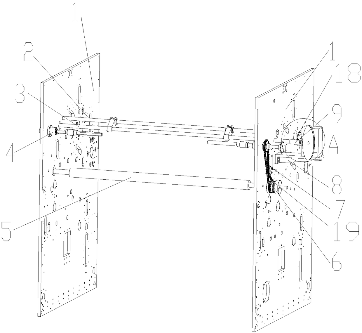
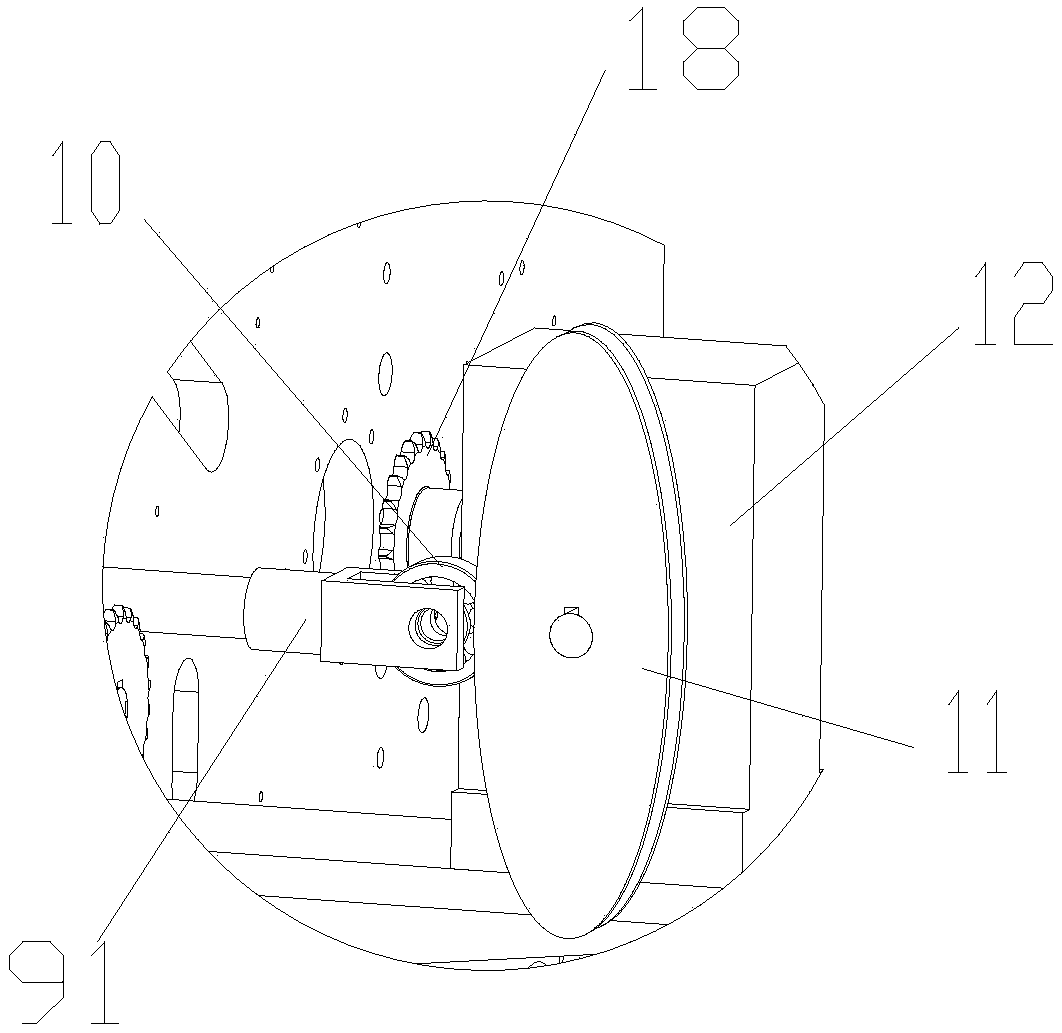
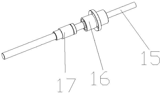
[0021] Such as Figure 1 to Figure 4 As shown, the embodiment of the present invention discloses a waste tape collection device for a tape slitting machine, including a wallboard 1, a guide shaft 2, a movement shaft 3, a ferrule 13, a waste collection shaft 15, a first The driving device and the second driving device, two wall boards 1 are parallel to each other, the guide shaft 2 is connected between the two wall boards 1 in rotation, the two ends of the moving shaft 3 pass through the two wall boards 1 respectively, and the moving shaft After one end of 3 passes through the corresponding wallboard 1, the axial movement is realized through the first driving device installed on the outside of the wallboard 1. The two ferrules 13 are respe...


PUM


Abstract

The invention discloses an adhesive tape scrap edge collecting device which comprises wallboards, a guiding shaft, a moving shaft, clamping sleeves, scrap collecting shafts, a first drive device and asecond drive device. The two wallboards are opposite in parallel; the guiding shaft is rotatably connected between the two wallboards; the two ends of the moving shaft penetrate through the two wallboards; a part, stretching out of the outer side of one wallboard, of one end of the moving shaft moves axially through the first drive device arranged on the outer side of the wallboard; the two clamping sleeves are close to the two wallboards and sleeve on the guiding shaft and the moving shaft between the two wallboards; the two scrap collecting shafts are arranged on the opposite inner sides ofthe two wallboards and are close to the moving shaft; and parts, stretching out of the outer sides of the wallboards, of the scrape collecting shafts rotate through the second drive device, so that scrap edges are collected. According to the adhesive tape scrap edge collecting device provided by the invention, a cam drives the moving shaft to enable the clamping sleeves to guide the scrap edges,so that a horizontal distance of scrap edge collection is increased, the scrap edge collection amount within each period is improved, the number of times of shutdown is reduced, and the utilization rate of the machine is improved.

Description

technical field [0001] The invention belongs to the technical field of mechanical processing, and in particular relates to a waste edge collecting device for adhesive tapes. Background technique [0002] The tape slitter is mainly used to cut a large bundle of tapes into several small tapes for daily use for sale and use, and the waste edges formed after cutting the tapes need to be collected. The waste edge of the traditional tape slitting machine is collected by nylon sleeves, so there is a certain limit to the waste collection distance, so that the amount of waste edges that can be collected by each nylon sleeve is relatively small, and when the nylon sleeve is full, it takes To replace the nylon sleeve, various restrictions lead to frequent replacement of the nylon sleeve. Every time the nylon sleeve is replaced, it needs to be shut down, which increases the number of shutdowns, reduces the effective working time of the machine, and also reduces the working efficiency of...

Claims


Application Information

Patent Timeline
IPC IPC(8): B65H35/00
CPCB65H35/0073
Inventor 刘博文刘爱忠鲁楠王佳琪韩雪
Owner BEIJING INSTITUTE OF GRAPHIC COMMUNICATION
Learn More