
Centrifugal pump, in particular circulation pump

A technology of centrifugal pumps and circulating pumps, which is applied in the field of circulating pumps and can solve problems such as degradation problems

Active Publication Date: 2018-08-03
KSB AG
View PDF6 Cites 0 Cited by
  • Summary
  • Abstract
  • Description
  • Claims
  • Application Information

AI Technical Summary

Problems solved by technology

Currently, manufacturers use these relatively expensive materials only for permanent magnets, whose ecological degradation becomes extremely problematic

Method used


Image

  • Centrifugal pump, in particular circulation pump
  • Centrifugal pump, in particular circulation pump
  • Centrifugal pump, in particular circulation pump

Examples


Embodiment Construction

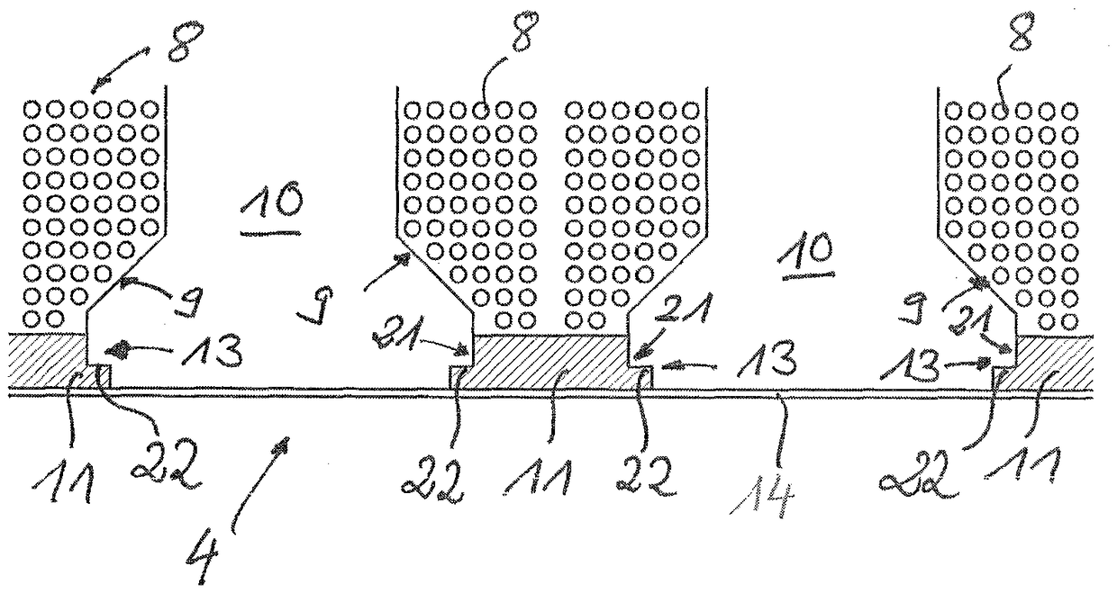
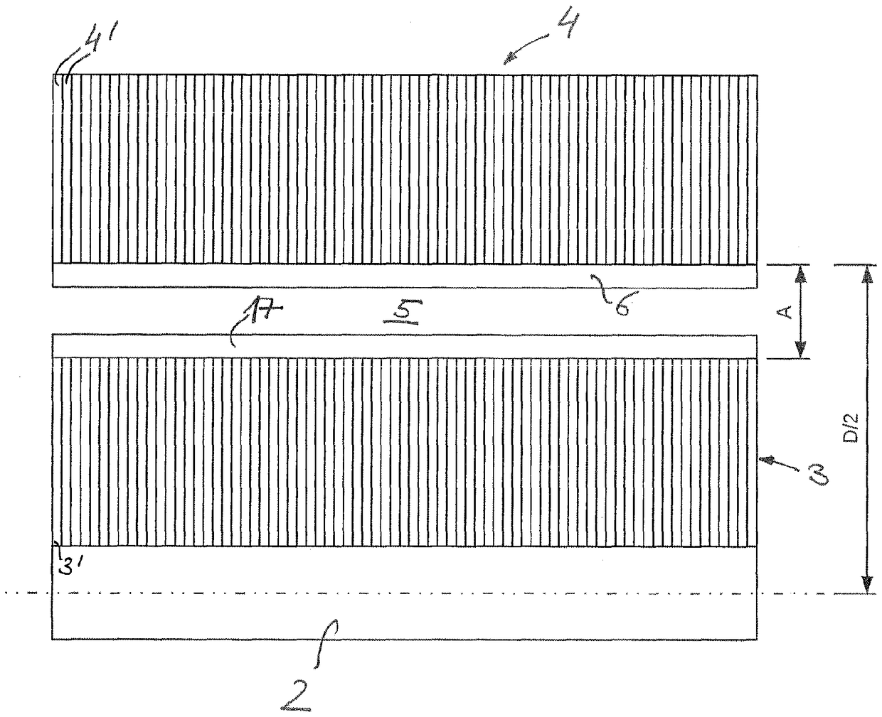
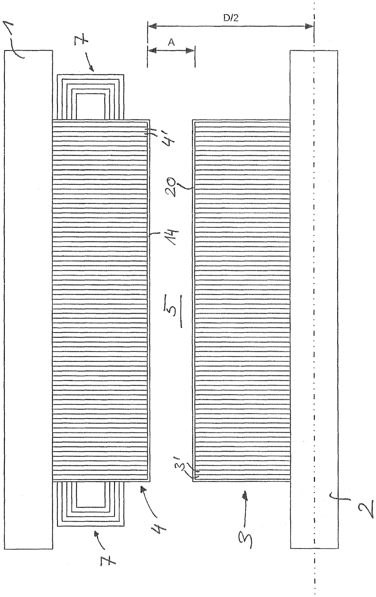
[0037] The following descriptions refer to, but are not limited to, circulator pumps and are generally applicable to any form of centrifugal pump. Figures 1 to 4 Different embodiment variants of the circulating pump are shown, and the figures show, in particular, a partial sectional view of a synchronous reluctance motor used for driving the circulating pump as an integral part of the pump housing. The basic construction is the same for all variants, ie the drive unit comprises a motor housing 1 with a mounted shaft 2 . Mounted on the shaft is a rotor 3 which runs in a stator bore of an outer stator 4 . Both the rotor 3 and the stator 4 consist of individual plate-like laminations 3 ′, 4 ′ respectively stacked in the axial direction to form a lamination pack. An air gap 5 is located between the rotor core 3 and the stator core 4 . According to the Vagati-Design of US Pat. No. 5,818,140, ​​the plate-like laminae 3' of the rotor 3 are preferably provided with flux suppression...


PUM


Abstract

The invention relates to a centrifugal pump, in particular a circulation pump, comprising a pump impeller and an integrated synchronous reluctance motor for driving the impeller, wherein the distanceA between the magnetically active components of the laminated stator core (4) and of the laminated rotor core (3) is less than or equal to 3% of the stator bore diameter and separating means for protecting the current-conducting elements of the stator (4) from the conveyed medium are provided.

Description

technical field [0001] The invention relates to a centrifugal pump, in particular a circulation pump, having a pump impeller driven by an electric motor. Background technique [0002] Centrifugal pumps, especially circulation pumps, are used in residential, office and commercial buildings to transport drinking, heating and cooling water between heat generators and heat consumers. For example, in single-family houses up to three circulation pumps are used, namely for transporting hot water (“heat pumps”), for circulating hot drinking water (“circulation pumps”) and for transporting solar thermal media (“solar pumps”) "). In infrastructure complexes (eg airports) several thousand circulation pumps are used in widely branched facilities. [0003] The integrated unit is called a circulation pump, which consists of a pump for transferring energy to the liquid heat transfer medium and includes an electric motor integrated into the pump, which drives the pump impeller. The Energ...

Claims


Application Information

Patent Timeline
Patent Type & Authority Applications(China)
IPC IPC(8): H02K5/128H02K5/124F04D13/06H02K19/14H02K1/24F04D1/00H02K1/27H02K1/04
CPCF04D1/00F04D13/0606F04D13/0626F04D13/064H02K19/14H02K1/04H02K5/124H02K5/128H02K2201/03H02K2213/03
Inventor P.豪克J.舒莱雷尔
Owner KSB AG
Learn More