
Hydrogeneration system of hydrogen compressor skid-mounted hydrogeneration equipment and hydrogeneration method thereof

A technology of hydrogenation equipment and hydrogenation system, which is applied in the field of hydrogenation stations, can solve the problems of large area of ​​hydrogenation stations, difficulty in flexible hydrogenation, etc., so as to achieve a small footprint, ensure normal use, and large hydrogen storage capacity. Effect

Active Publication Date: 2018-08-03
上海氢枫能源技术有限公司
View PDF8 Cites 14 Cited by
  • Summary
  • Abstract
  • Description
  • Claims
  • Application Information

AI Technical Summary

Problems solved by technology

[0006] In view of the above-mentioned shortcomings of the prior art, the object of the present invention is to provide a hydrogenation system and a hydrogenation method of a skid-mounted hydrogenation equipment with a hydrogen compressor, which is used to solve the problem that the hydrogenation station occupies a large area in the prior art. , the problem of difficulty in flexible hydrogenation

Method used


Image

  • Hydrogeneration system of hydrogen compressor skid-mounted hydrogeneration equipment and hydrogeneration method thereof
  • Hydrogeneration system of hydrogen compressor skid-mounted hydrogeneration equipment and hydrogeneration method thereof

Examples


Embodiment Construction

[0048] The implementation of the present invention will be illustrated by specific specific examples below, and those skilled in the art can easily understand other advantages and effects of the present invention from the contents disclosed in this specification.

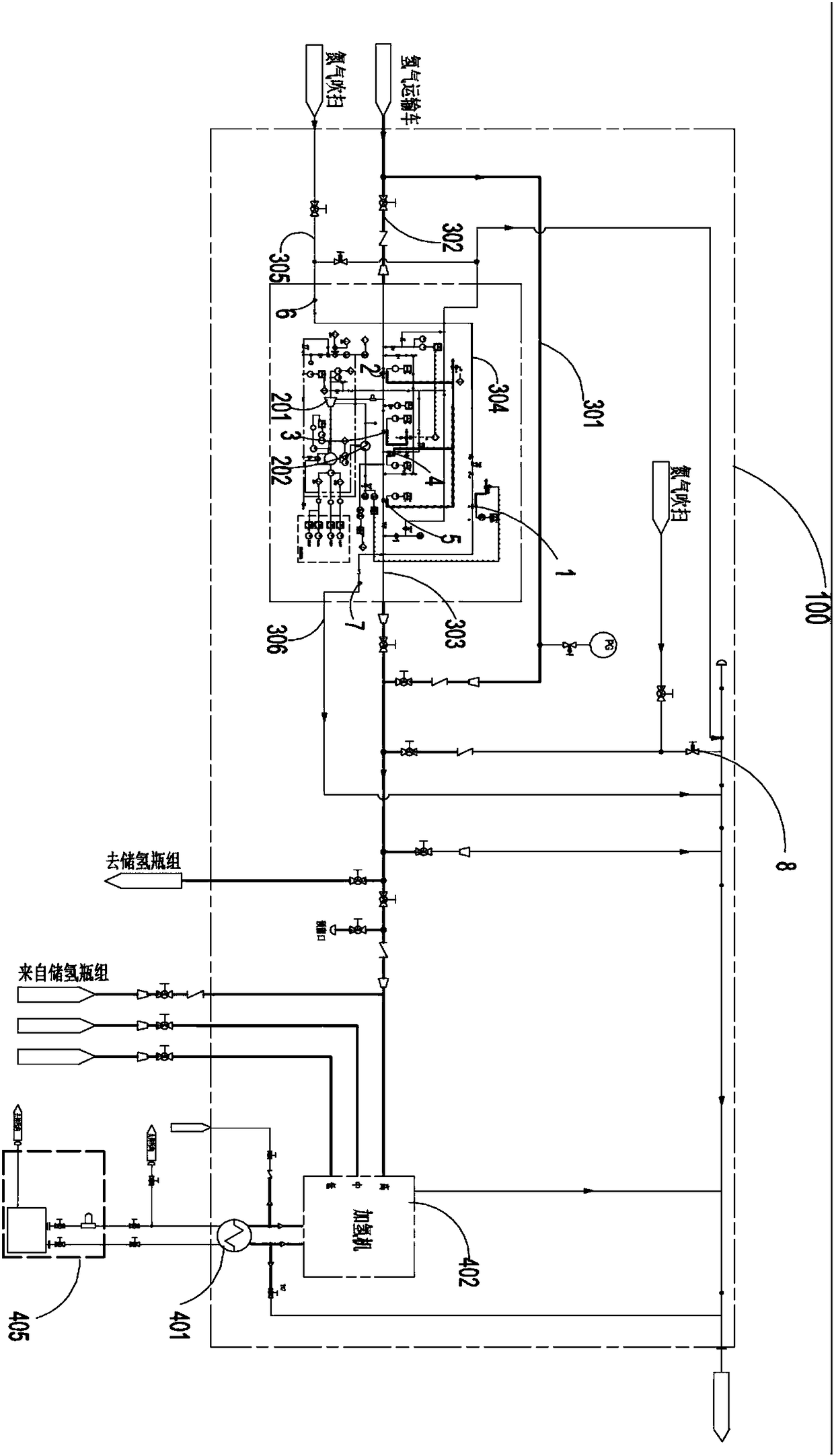
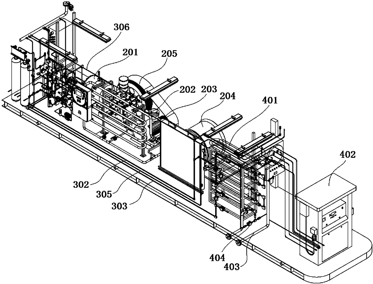
[0049] see Figure 1 to Figure 2 . It should be noted that the structures, proportions, sizes, etc. shown in the drawings attached to this specification are only used to match the content disclosed in the specification, for those who are familiar with this technology to understand and read, and are not used to limit the implementation of the present invention. Limiting conditions, so there is no technical substantive meaning, any modification of structure, change of proportional relationship or adjustment of size, without affecting the effect and purpose of the present invention, should still fall within the scope of the present invention. within the scope covered by the disclosed technical content. At the same ti...


PUM


Abstract

The invention provides a hydrogeneration system of hydrogen compressor skid-mounted hydrogeneration equipment and a hydrogenation method. The system comprises the following components arranged insidea skid-mounted shell: a pressurizing component, a hydrogen dispenser, a circulation loop and a controller, wherein a gas inlet of a diaphragm compressor in the pressurizing component is connected witha hydrogen inlet pipe, the end of the hydrogen inlet pipe is provided with an input end connected with a gas outlet of a hydrogen transporting truck, a gas outlet of the diaphragm compressor is connected with a hydrogen outlet pipe, and hydrogen in the hydrogen outlet pipe is cooled when flowing through a first cooling heat exchange element; a gas inlet pipeline of the hydrogen dispenser is connected with the hydrogen outlet pipe, and hydrogen in the gas inlet pipeline is cooled when flowing through a second cooling heat exchange element; one end of the circulation loop communicates with thehydrogen inlet pipe, and the other end of the circulation loop communicates with the hydrogen outlet pipe; and a first control valve, a second control valve and a third control valve which are used for controlling on and off of the pipelines are arranged on the hydrogen inlet pipe, the hydrogen outlet pipe and the circulation loop correspondingly, and are all connected with the controller. The whole hydrogeneration system is compact in structural arrangement, small in occupied area, and large in hydrogeneration capacity.

Description

technical field [0001] The invention relates to the technical field of hydrogen refueling stations, in particular to a hydrogen refueling system and a hydrogen refueling method of hydrogen compressor skid-mounted hydrogen refueling equipment. Background technique [0002] Due to its high efficiency and zero emissions, hydrogen fuel cell vehicle technology has become the most ideal and most likely technology to replace traditional vehicle power systems in this century. The development of fuel cell vehicle technology will completely solve the energy and environmental problems brought about by the development of vehicles at the same time, and truly realize the sustainable development of the automobile industry. All of their companies have stepped up research and development and demonstration of fuel cell vehicles and made significant progress. It is expected that fuel cell vehicles will officially enter the market in the next 5 to 10 years. Fuel cell vehicles use hydrogen as f...

Claims


Application Information

Patent Timeline
Patent Type & Authority Applications(China)
IPC IPC(8): F17C5/06F17C13/02F17C13/04F17C13/00
CPCF17C5/06F17C13/002F17C13/025F17C13/04F17C2225/0123F17C2223/0123F17C2221/012F17C2227/039F17C2227/0337F17C2227/0157F17C2265/063F17C2250/043F17C2270/0184F17C2201/056Y02P90/45Y02E60/32
Inventor 宣锋石祥方沛军陈笠田丽莉邹吉丹孟凡涛
Owner 上海氢枫能源技术有限公司
Learn More