
Coring drill suitable for asphalt road surface and coring machine

A technology for asphalt pavement and coring drills, which is applied to roads, drill bits, roads, etc., can solve the problems of shortening the service life of the coring drill, breaking the core sample, destroying the structural accuracy of the coring machine, etc., and achieves the effect of avoiding the expansion of the gap.

Pending Publication Date: 2018-08-03
ZHANJIANG JIANKE ENG QUALITY TESTING CENT CO LTD
View PDF0 Cites 0 Cited by
  • Summary
  • Abstract
  • Description
  • Claims
  • Application Information

AI Technical Summary

Problems solved by technology

[0004] Therefore, the technical problem to be solved by the present invention is to overcome the defects in the prior art that the service life of the core drill is shortened, the structural accuracy of the coring machine is destroyed, and the core sample is easily broken during the process of taking out the core sample from the core drill. , and further provide a kind of coring drill and coring machine applied to asphalt pavement that can prolong the service life of the core drill itself, is not easy to damage the accuracy of the coring machine, and is not easy to cause the core sample to break

Method used


Image

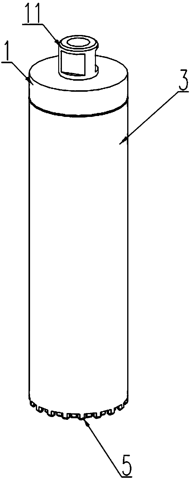
  • Coring drill suitable for asphalt road surface and coring machine
  • Coring drill suitable for asphalt road surface and coring machine
  • Coring drill suitable for asphalt road surface and coring machine

Examples


Embodiment 1

[0044] Such as Figure 1 to Figure 5 As shown, it is Embodiment 1 of the present invention. This embodiment provides a coring drill suitable for asphalt pavement, which is used to be installed on a coring machine for drilling and coring the asphalt pavement. This embodiment includes a drill handle 1 and a drill body, the drill handle 1 has a clamping portion 11 suitable for connecting with the main shaft of a coring machine; the drill body is cylindrical, connected with the drill handle 1, and the drill The end of the body away from the drill shank 1 is provided with several cutting teeth 5, and the cutting teeth 5 are suitable for circular motion following the drill body and cutting the road surface; the drill body includes a cylindrical liner, and the liner is composed of At least two bar-shaped drill pieces 2 with arc-shaped cross-sections are assembled. The central angle corresponding to any cross-section of any one of the drill pieces 2 is not greater than 180°. The drill...

Embodiment 2

[0056] This embodiment provides a coring machine. The lower end of the main shaft of the coring machine is equipped with the core drill provided in Embodiment 1. This embodiment relies on driving the core drill to rotate, and then splits the asphalt pavement.

[0057] Since the present embodiment is equipped with the coring drill provided in embodiment 1, it has all the advantages brought by the coring drill provided in embodiment 1.


PUM


Abstract

The invention provides a coring drill suitable for an asphalt road surface and a coring machine and belongs to the technical field of road maintenance. The coring drill comprises a drill handle and adrill body, wherein the drill handle is provided with a clamping portion to be connected with a spindle of the coring machine, the drill body is cylinder and is connected with the drill handle, and aplurality of cutting teeth are arranged at the end, away from the drill handle, of the drill body and are suitable for circling motion by following the drill body and road surface segmentation. The drill body comprises a cylindrical bushing, wherein the cylindrical bushing is formed by splicing at least two strip-shaped drill pieces with arc-shaped cross sections, the central angle corresponding to any one cross section of any one drill piece is not greater than 180 degrees, and the drill pieces are detachably connected with the drill handle. A core sample can be smoothly taken from the coringdrill, and breakage and bump of the core sample are avoided. In addition, the coring drill also has the advantages of being long in service life, reasonable in assembly structure, good in stress performance, convenient to dismount and the like.

Description

technical field [0001] The invention relates to the technical field of road maintenance, in particular to a coring drill and a coring machine suitable for asphalt pavement. Background technique [0002] In the process of daily maintenance of asphalt pavement, it is necessary to obtain parameters such as the degree of compaction of the pavement and the thickness of the structural layer. In order to obtain these parameters, core samples of asphalt pavement are generally obtained by punching and coring in the prior art. The coring process is generally divided into two stages: the first drilling stage, at this stage the coring machine drives the core drill to rotate, the core drill is a hollow cylindrical structure, and the lower edge of the core drill is equipped with cutting teeth , through the contact and friction between the cutting teeth and the road surface, the core drill is drilled vertically into the interior of the asphalt pavement; the second step is the coring stage...

Claims


Application Information

Patent Timeline
Patent Type & Authority Applications(China)
IPC IPC(8): E21B7/00E21B10/42E21B10/633E01C23/01
CPCE21B7/00E21B10/42E21B10/633E01C23/01
Inventor 周大强
Owner ZHANJIANG JIANKE ENG QUALITY TESTING CENT CO LTD
Learn More