
Unmanned aerial vehicle remote video pushing method based on cloud side

A technology for remote video and drones, applied in the field of remote video push of drones, can solve the problem that drones are difficult to achieve remote and free real-time video transmission of multiple drones, and overcome geographical and distance limitations. The effect of ensuring reliability and stability

Inactive Publication Date: 2018-07-31
南京奇蛙智能科技有限公司
View PDF10 Cites 11 Cited by
  • Summary
  • Abstract
  • Description
  • Claims
  • Application Information

AI Technical Summary

Problems solved by technology

[0004] The purpose of the present invention is to provide a cloud-based UAV remote video push method to solve the technical problem that it is difficult for UAVs to realize real-time free transmission of remote and multi-UAV videos in the prior art

Method used


Image

  • Unmanned aerial vehicle remote video pushing method based on cloud side
  • Unmanned aerial vehicle remote video pushing method based on cloud side
  • Unmanned aerial vehicle remote video pushing method based on cloud side

Examples


Embodiment 1

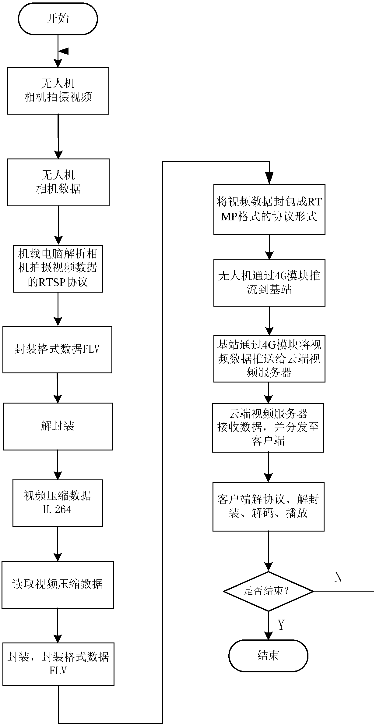
[0035] A cloud-based UAV remote video push method, comprising the following steps, such as image 3 Shown:

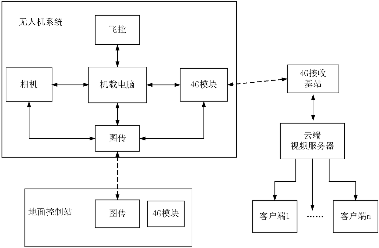
[0036]1) Build a UAV remote video push system: The UAV remote video push system includes multiple clients, cloud video servers, base stations, ground control stations and UAVs; UAVs are equipped with on-board computers, unmanned UAV controller, camera, image transmission module and 4G module, the UAV controller communicates with the onboard computer through the CAN bus, and the image transmission module, camera and 4G module communicates with the onboard computer through the network port; the ground control station includes a 4G module and image transmission module; base station and cloud video server through 4G communication; cloud video server and multiple clients communicate through 4G wireless communication module, such as figure 1 shown;

[0037] 2) During the long-distance flight of the UAV, the environment where the UAV is located has a good 4G signal, and the ...

Embodiment 2

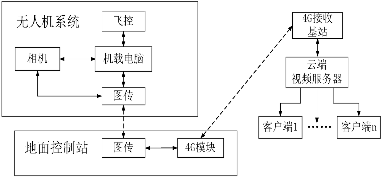
[0056] In Step 2) of Embodiment 1, when the 4G signal at the location of the ground control station is good, and the video push delay requirement is low due to the transmission delay of the image transmission module, the onboard computer performs the above-mentioned processing on the video collected by the camera , the UAV will transmit the video data to the ground control station through the image transmission module, and then push the video to the remote base station through the 4G module of the ground control station; after the base station receives the video data, it will push the video data to the cloud through the 4G module The video server, the cloud video server distributes the packaged video data to the required clients according to the needs of the client; the client performs the protocol, decapsulation, decoding, and synchronization processing on the data of the RTMP protocol, and then plays it, such as figure 2 shown. Other parts are the same as in Embodiment 1. ...


PUM

PropertyMeasurementUnit
Resolutionaaaaaaaaaa

Abstract

The invention discloses an unmanned aerial vehicle remote video pushing method based on a cloud side. Multiple clients, a cloud side video server, a base station, a ground control station and an unmanned aerial vehicle are provided; the real-time pushing and watching of the unmanned aerial vehicle remote video can be realized by means of the cloud-side video server system of the 4G, thereby overcoming the territory and distance limitation, and the demand of simultaneously watching the pushed video by multiple clients can be satisfied; the 4G module is respectively installed on the unmanned aerial vehicle system and the ground station so as to produce two sets of solutions with the same functions and different application scenes, thereby ensuring the reliability and stability of the remotevideo pushing at the cloud side. The current popular video live technology is applied to the unmanned aerial vehicle field, the remote live of the unmanned shot video is performed by sufficiently utilizing the internet and the streaming media technology.

Description

technical field [0001] The invention belongs to the field of remote control of unmanned aerial vehicles, and in particular relates to a remote video push method for unmanned aerial vehicles based on a 4G module cloud video server, which uses video live broadcast technology for reference, overcomes distance limitations, and realizes real-time push and viewing of camera videos. Background technique [0002] As the technology of drones becomes more and more mature, the application fields of drones are becoming more and more extensive. Man-machine, aerial photography UAV, reconnaissance UAV, etc. [0003] At present, most of the videos shot by drone-side cameras are pushed by image transmission, which can realize short-distance transmission, mostly several kilometers or even tens of kilometers. performance of the UAV. Most of the videos pushed at the same time only allow one terminal to watch, which is difficult to meet the needs of multiple clients in different locations to w...

Claims


Application Information

Patent Timeline
IPC IPC(8): H04L29/06H04L29/08H04N19/44H04B7/185H04L12/40
CPCH04B7/18506H04B7/18517H04L12/40006H04L67/025H04N19/44H04L2012/40215H04L65/75H04L65/65H04L67/55
Inventor 廖振星段文博高月山张伟
Owner 南京奇蛙智能科技有限公司
Learn More