
Automobile part quenching device

A technology for auto parts and quenching devices, applied in quenching devices, heat treatment equipment, manufacturing tools, etc., can solve the problems of oil fume emission, poor condensation effect of condenser, excessive adhesion of oil fumes, etc., and achieve environmental protection and energy saving in driving mode Production cost, effect of guaranteed treatment effect

Inactive Publication Date: 2018-07-27
NINGBO HAIMAN AUTOMOTIVE TECH CO LTD
View PDF3 Cites 4 Cited by
  • Summary
  • Abstract
  • Description
  • Claims
  • Application Information

AI Technical Summary

Problems solved by technology

[0004] However, the above-mentioned patents have the following problems: the generated oily fume will cool and stick to the condenser after contacting the condenser for condensation. After repeated use, the surface of the condenser will have too much oily fume, which will lead to poor condensation effect of the condenser. A large amount of oil fume is emitted into the air

Method used


Image

  • Automobile part quenching device
  • Automobile part quenching device

Examples


Embodiment Construction

[0019] The present invention will be described in further detail below by means of specific embodiments:

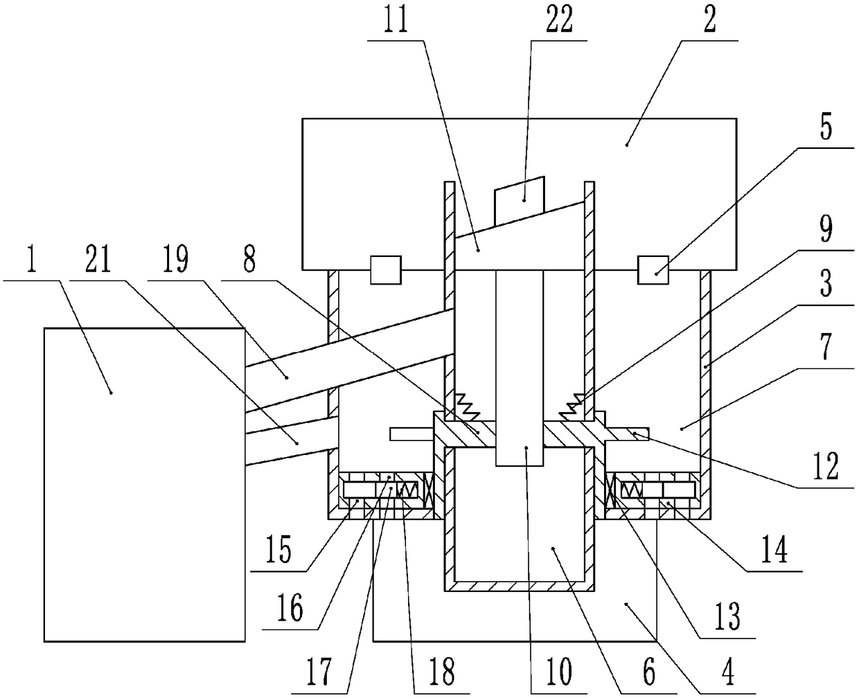
[0020] The reference signs in the drawings of the specification include: quenching box 1, heating box 2, air intake box 3, flue gas treatment box 4, solenoid valve 5, slideway 6, air inlet 7, turntable 8, first torsion spring 9 , screw 10, workpiece table 11, paddle 12, one-way bearing 13, gas distribution plate 14, air inlet 15, air outlet 16, valve core 17, spring 18, workpiece discharge groove 19, rotating plate 20, smoke exhaust pipe 21. Workpiece 22.

[0021] Such as figure 1 and figure 2 As shown, the quenching device for auto parts includes a quenching box 1 and a heating box 2 connected sequentially from top to bottom, an air intake box 3 and a flue gas treatment box 4. The connection between the heating box 2 and the air intake box 3 is installed with two A solenoid valve 5, a sleeve is installed in the air intake box 3, the sleeve divides the air intake box ...


PUM


Abstract

The invention belongs to equipment for metal heat treatment and particularly relates to an automobile part quenching device. The automobile part quenching device comprises a quenching box, a heating box, an air feeding box and a flue gas processing box, wherein the heating box, the air feeding box and the flue gas processing box communicate with one another. The heating box is provided with valves. The air feeding box is internally provided with an air feeding channel and a sliding channel. The sliding channel is internally and rotatably connected with a rotary table, the rotary table is connected with a threaded rod in a threaded manner, and the threaded rod is fixedly connected with a workbench. The air feeding channel is internally and rotatably connected with a blade, first torsional springs are connected between the rotary table and the sliding channel. The rotary table is further rotatably connected with an air distribution disc, the air distribution disc is provided with an airinlet and an air outlet, and the air distribution disc is internally provided with a valve core for blocking the air inlet or the air outlet. The air feeding box is internally provided with a workpiece discharging slot, the workpiece discharging slot is formed between the sliding channel and the quenching box in a communicating manner, and the quenching box is further provided with a pipe communicating with the air feeding channel. By the adoption of the automobile part quenching device, the soot generated by oil quenching can be collected and processed, direct emission of the soot is reduced,and the automobile part quenching device is more environmentally friendly and is mostly used for oil quenching machining of automobile parts.

Description

technical field [0001] The invention belongs to equipment for metal heat treatment, in particular to a quenching device for auto parts. Background technique [0002] Vacuum oil quenching furnace is suitable for vacuum heat treatment of die steel, spring steel, stainless steel, bearing steel, high temperature alloy steel, etc. Its main features are a wide range of applicable materials, strong hardenability, low cost, and reusable quenching oil. However, when the existing vacuum oil quenching furnace is used, during the process of processing workpieces into the oil, due to the high temperature of the workpieces, the oil will evaporate rapidly due to the instantaneous quenching of the oil, which will generate a large amount of oily fumes. When the workpieces are released from the furnace, the oily fumes will be lost to the air In the process, the pollution to the environment is caused, and the quenching oil is also consumed quickly, which does not conform to the current produc...

Claims


Application Information

Patent Timeline
Patent Type & Authority Applications(China)
IPC IPC(8): C21D1/63C21D1/773
CPCC21D1/63C21D1/773
Inventor 项文增
Owner NINGBO HAIMAN AUTOMOTIVE TECH CO LTD
Learn More