
Pole plate weighing instrument for storage battery

A weighing instrument and battery technology, applied in the field of battery electrode plate weighing instrument, can solve the problems of insufficient environmental protection and energy saving driving mode, inability to fix the electrode plate, easy sliding out of the electrode plate, etc. Robust, easy-to-install effect

Inactive Publication Date: 2018-07-10
明光市振宇电源有限公司
View PDF0 Cites 0 Cited by
  • Summary
  • Abstract
  • Description
  • Claims
  • Application Information

AI Technical Summary

Problems solved by technology

[0002] The existing weighing instrument refers to that when the object is placed on the weighing pan, the pressure is applied to the sensor, and the sensor undergoes elastic deformation, thereby changing the impedance and changing the excitation voltage at the same time, outputting a changed analog signal, the signal After being amplified by the amplifier circuit, it is amplified and output to the analog-to-digital converter, converted into a digital signal that is easy to process and output to the CPU operation control, and the CPU outputs the result to the display according to the keyboard command and program; Certain disadvantages, the traditional plate weighing instrument cannot fix the plate when weighing the plate, making the plate easy to slide out of the weighing instrument, the traditional plate weighing instrument uses lithium battery for power supply, driving The method is not environmentally friendly and energy-saving. When the traditional plate weighing instrument is placed on the table, when the table shakes, the plate weighing instrument will also tilt, and the fixing effect is poor, which has brought a certain impact on the user. For this reason, we propose a battery plate weighing instrument

Method used


Image

  • Pole plate weighing instrument for storage battery
  • Pole plate weighing instrument for storage battery
  • Pole plate weighing instrument for storage battery

Examples


Embodiment Construction

[0017] In order to make the technical means, creative features, objectives and effects of the present invention easy to understand, the present invention will be further explained below in conjunction with specific embodiments.

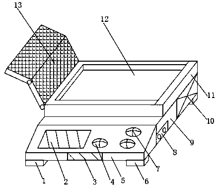
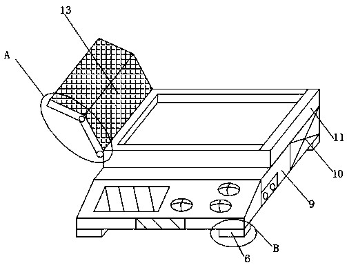
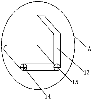
[0018] Such as Figure 1-4 As shown, a plate weighing instrument for a battery includes a controller 5 and a weighing instrument body 9. A power button 4 is fixedly installed on the outer surface of the upper end of the controller 5, and the upper inner surface of the controller 5 is close to the power button 4 A display panel 2 is fixedly installed on one side of the controller 5, a control button 7 is fixedly installed on the outer surface of the upper end of the controller 5 close to the power button 4, and a mark is fixedly installed on the outer surface of the front end of the controller 5 close to the power button 4 Nameplate 3, the outer surface of the lower end of the controller 5 is fixedly installed with a fixed leg 1, and the outer surface of ...


PUM


Abstract

The invention discloses a pole plate weighing instrument for a storage battery, and the weighing instrument comprises a controller and a weighing instrument main body. The external surface of the upper end of the controller is fixedly provided with a power key. One side, close to the power key, of the internal surface of the upper end of the controller is fixedly provided with a display panel, andthe other side, close to the power key, of the external surface of the upper end of the controller is fixedly provided with a control key. Moreover, a lower part, close to the power key, of the external surface of the front end of the controller is fixedly provided with a mark nameplate, and the external surface of the lower end of the controller is fixedly provided with a first fixed leg. Moreover, one side, close to the first fixed leg, of the external surface of the lower end of the controller is fixedly provided with a second fixed leg. The weighing instrument provided by the invention isprovided with an accommodation groove, a solar cell panel and the second fixed leg, can achieve the fixing of a pole plate, enables a drive mode to be more environment-friendly, improves the placement stability, and is better in application prospect.

Description

Technical field [0001] The invention relates to the field of weighing instrument equipment, in particular to a plate weighing instrument for storage batteries. Background technique [0002] The existing weighing instrument means that when an object is placed on the weighing pan, pressure is applied to the sensor, and the sensor undergoes elastic deformation, thereby changing the impedance and at the same time changing the excitation voltage, outputting a changing analog signal. The amplifying circuit amplifies and outputs it to the analog-to-digital converter, converts it into a digital signal that is easy to process, and outputs it to the CPU operation control. The CPU outputs this result to the display according to keyboard commands and programs; the existing plate weighing instrument exists when in use Certain disadvantages, the traditional plate weighing instrument cannot fix the plate when weighing the plate, which makes the plate easy to slide out of the weighing instrument...

Claims


Application Information

Patent Timeline
Patent Type & Authority Applications(China)
IPC IPC(8): G01G19/62G01G21/02G01G21/22
CPCG01G19/62G01G21/02G01G21/22
Inventor 严毅
Owner 明光市振宇电源有限公司
Learn More