
Focal plane rotating laser spot welding method

A technology of laser spot welding and welding method, which is applied in the field of material processing to achieve the effects of good weld quality, obvious technological advantages and increased weld width to depth ratio.

Active Publication Date: 2018-07-27
BEIJING UNIV OF TECH
View PDF7 Cites 10 Cited by
  • Summary
  • Abstract
  • Description
  • Claims
  • Application Information

AI Technical Summary

Problems solved by technology

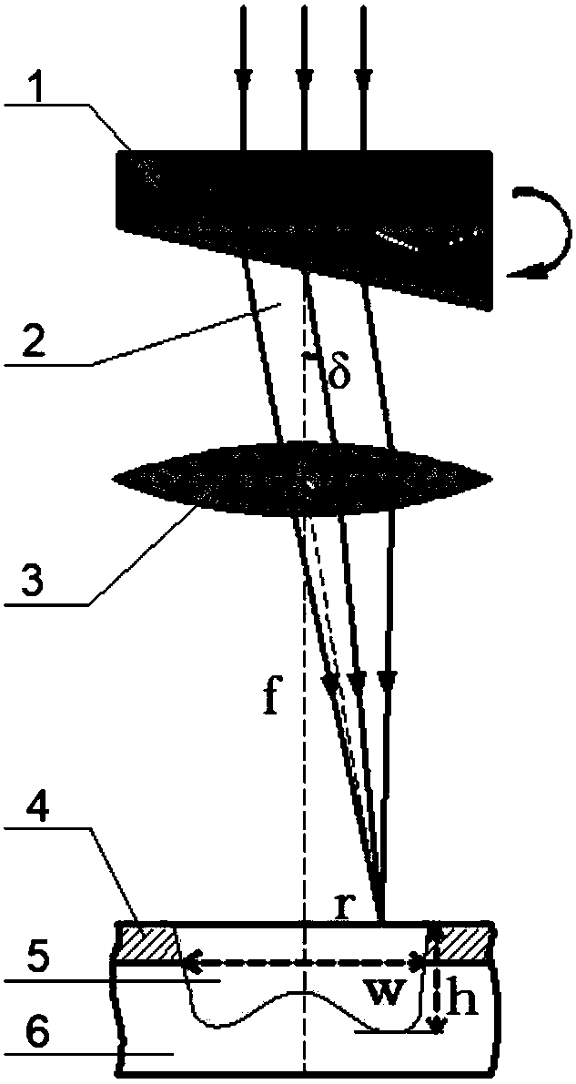
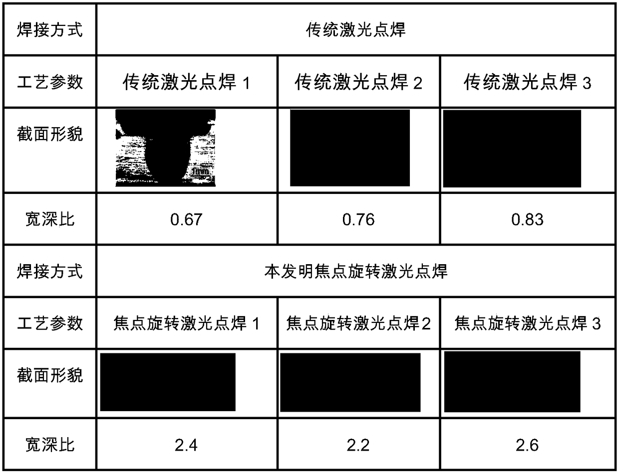
[0004] The purpose of the present invention is to provide a focus rotation laser spot welding welding method, which can effectively solve the limitation of the effective melting width of the welding spot by the interface thermal resistance in the traditional laser lap spot welding, and greatly improve the width-to-depth ratio (w / h) of the welding spot , and the welding process is stable, free of defects such as spatter, settling, and cracks, and is suitable for laser spot welding of metal materials

Method used


Image

  • Focal plane rotating laser spot welding method
  • Focal plane rotating laser spot welding method
  • Focal plane rotating laser spot welding method

Examples


Embodiment 1

[0015] The equipment used includes: wedge lens, focusing lens, upper plate material, laser. From top to bottom, there are lasers, wedge lenses, focusing lenses, and upper plate materials. The laser emits parallel beams, and the parallel beams are vertical to the upper surface of the wedge lens, and then pass through the oblique lower surface of the wedge lens to reach the focus lens. The focus shift reaches the surface of the upper plate material, and during the welding process, the wedge-shaped lens is rotated at a constant speed, so that the focus is in a uniform circular motion on the upper plate material.

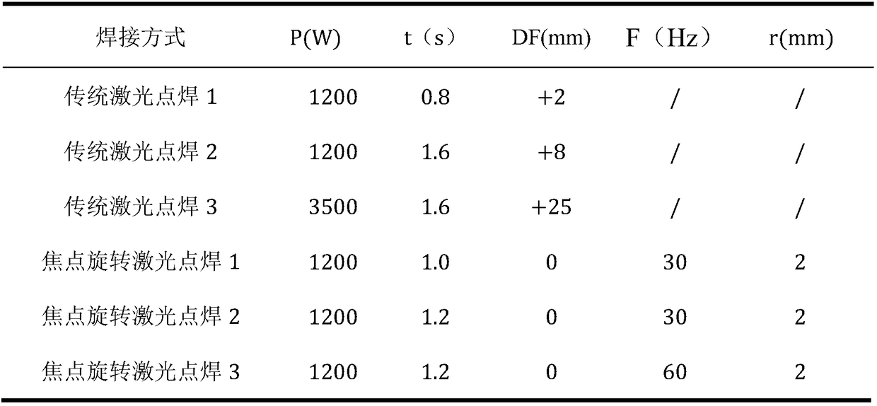
[0016] Embodiment 1 welding process parameter is as shown in the table below:

[0017]

[0018] Among them, P is the laser power, t is the spot welding time, DF is the defocus amount, and it is positive if the focus is on the surface of the workpiece, F is the focus rotation frequency, and r is the focus rotation radius. The laser used in this example is IPG-YLS6000 ...


PUM


Abstract

The invention discloses a focal plane rotating laser spot welding method suitable for laser spot welding of a metal material. The focal plane rotating laser spot welding method is characterized in that laser light spots perform small-radius, high-frequency and uniform-speed circular motion on the surface of a workpiece. During welding, the focus rotational frequency is 10-120HZ; the focus rotational radius is 1.0-2.5mm; the laser power is 600-3000W; the spot welding time is 0.4-3.0S; and the defocusing amount is -3-+3mm. The focal plane rotating laser spot welding method has the beneficial effects that by matching focus rotation parameters and welding technological parameters, a novel weld appearance based on heat conduction welding in a mode of repeated welding heat accumulation is acquired, is large in the width-depth ratio (effective melting width / melting depth) and does not have the defects of stomata, cracks, collapses and the like. Compared with the traditional laser spot welding, by adopting the focal plane rotating laser spot welding method, the welding process is stable, the weld quality is better, the influence on the effective melting width (fusion area melting width) bythermal contact resistance between lapping interfaces can be neglected, the weld width-depth ratio is greatly increased, and the focal plane rotating laser spot welding method has obvious technological advantages.

Description

technical field [0001] The invention relates to a focus rotating laser spot welding welding method capable of obtaining a large width-to-depth ratio (effective melting width w / penetration depth h) spot welding seam appearance. The specific method is to use a beam control method to make the laser focus a small radius and high Frequency constant rotation, so as to perform rapid and repeated welding. This welding method can obtain a spot welding seam morphology with a large width-to-depth ratio (w / h), which changes the "nail head" weld seam shape of the traditional laser spot welding with a large depth-to-width ratio. It has obvious advantages in spot welding and belongs to the field of material processing technology. Background technique [0002] In the field of laser processing, laser spot welding has many advantages compared with resistance spot welding, such as high precision, precise energy control, good penetration, and small welding thermal deformation. Automobile and ...

Claims


Application Information

Patent Timeline
IPC IPC(8): B23K26/22
CPCB23K26/22
Inventor 肖荣诗彭书胜武强
Owner BEIJING UNIV OF TECH
Learn More