Mode switch with network control and switching method
A mode switch, network control technology, applied in the direction of program control, computer control, general control system, etc., can solve the problems of high production cost, many wiring harness loops, etc., to achieve less error-prone, reduce the number of loops, simple and clear operation mode Effect
- Summary
- Abstract
- Description
- Claims
- Application Information
AI Technical Summary
Problems solved by technology
Method used
Image
Examples
Embodiment 1
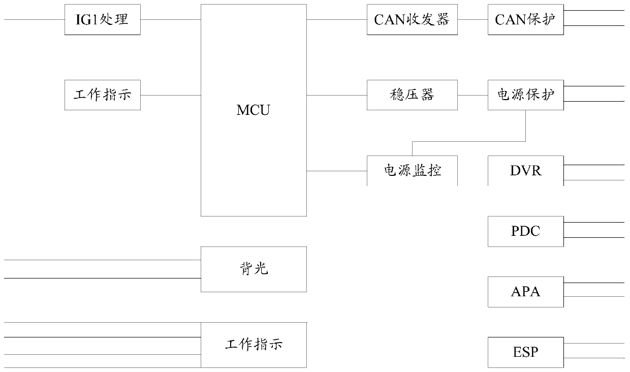
[0041] figure 1 It is a schematic diagram of the hardware architecture of the driving mode switch module DMS of the present invention, which includes a micro control unit MCU, a CAN transceiver and a power supply. The micro control unit MCU is the main unit for storing and executing the program. It analyzes the input signal and sends the corresponding signal. In the present invention, the micro control unit MCU can process the input switch signal and drive the LED light The micro control unit MCU chip model that the present invention adopts is S12G64, and main parameter is 64KB FLASH, 4KB RAM, 2KB EEPROM, and under STOP mode, typical power consumption is 25uA. The CAN transceiver is used to send and receive CAN signals. It is a device that connects the CAN bus and the MCU, and converts the signals between the two to meet the requirements of the CAN bus and the MCU for CAN signals. ; The chip model of the CAN transceiver adopted by the present invention is TJA1044, and the low...
Embodiment 2
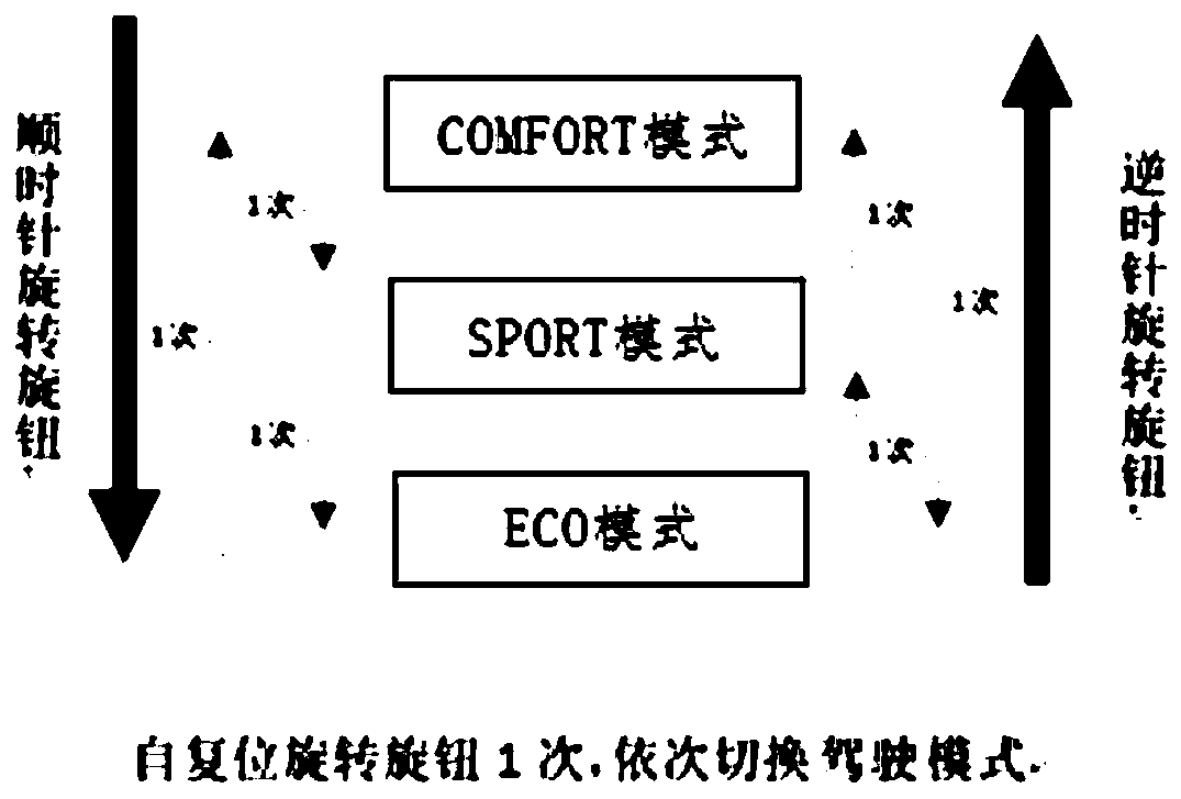
[0043] figure 2 It is a schematic diagram of the switching process of the driving mode switch. The driving mode switch is a self-resetting knob switch, which can realize switching between three driving modes COMFORT mode, SPORT mode and ECO mode. Rotate the self-resetting knob switch to switch in turn driving mode.
[0044] For example, if the current driving mode is COMFORT mode, turn the knob clockwise once to switch to SPORT mode, and turn the knob clockwise once again to switch to ECO mode; at this time, turn the knob clockwise once again, Switched to the COMFORT mode again, realizing the cycle switching of the driving mode.
[0045] If the current driving mode is ECO mode, turn the knob switch counterclockwise once to switch to SPORT mode, and turn the knob switch counterclockwise once again to switch to COMFORT mode; Can switch to ECO mode.
[0046] The switching of the driving mode can also be realized through the combined operation of the switch clockwise and count...
Embodiment 3
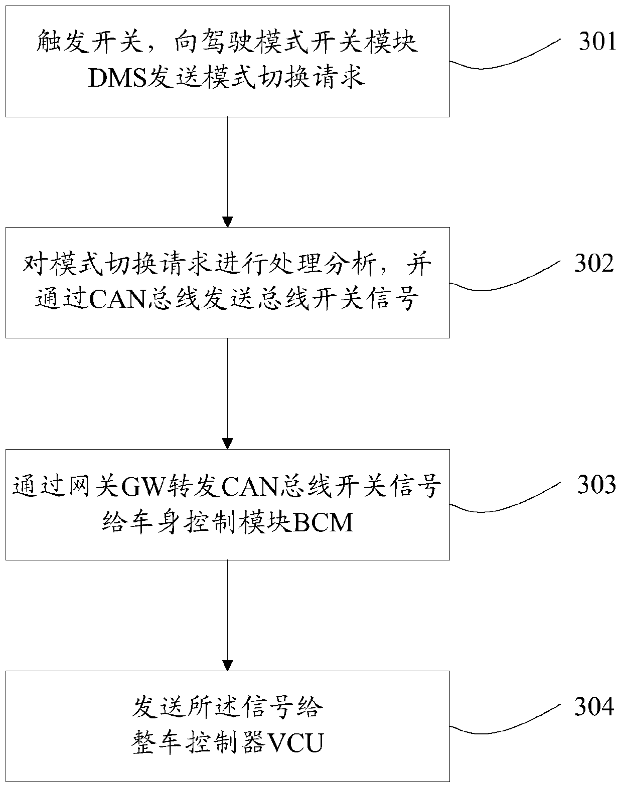
[0048] image 3 It is a flow chart of a mode switching method with network control in the present invention, including:
[0049] S301. Trigger the switch, and send a mode switching request to the driving mode switch module DMS.
[0050] Specifically, the mode switching includes vehicle mode switching and driving mode switching.
[0051] S302. Process and analyze the mode switch request, and send a bus switch signal through the CAN bus.
[0052] Specifically, the micro control unit MCU in the driving mode switch module DMS analyzes and processes the received switch signal, and sends it out through the CAN bus transceiver.
[0053] S303. Forward the CAN bus switch signal to the body control module BCM through the gateway GW.
[0054] Specifically, the gateway GW is used to connect two CAN communication networks with different rates.
[0055] S304. Send the signal to the vehicle controller VCU.
[0056] Specifically, the vehicle body control module BCM sends signals to the v...
PUM
 Abstract
Description
Claims
Application Information
 - R&D Engineer
- R&D Manager
- IP Professional
- Industry Leading Data Capabilities
- Powerful AI technology
- Patent DNA Extraction
Browse by: Latest US Patents, China's latest patents, Technical Efficacy Thesaurus, Application Domain, Technology Topic, Popular Technical Reports.
© 2024 PatSnap. All rights reserved.Legal|Privacy policy|Modern Slavery Act Transparency Statement|Sitemap|About US| Contact US: help@patsnap.com


