Construction material conveying apparatus

A technology for conveying devices and buildings, which is used in hoisting devices, transportation and packaging, lifting equipment braking devices, etc. The effect of high degree and easy operation and control

Pending Publication Date: 2018-07-24
岳晓楠
View PDF0 Cites 1 Cited by
  • Summary
  • Abstract
  • Description
  • Claims
  • Application Information

AI Technical Summary

Problems solved by technology

In the past, some construction equipment was mostly suitable for the construction of old-fashioned houses. When building small buildings such as two-story buildings and three-story buildings, it is difficult for some existing construction equipment to meet the requirements for building use. When building low-rise buildings by means of manual transportation, etc., mechanization and automatic transportation of materials cannot be realized, which not only greatly increases construction costs such as labor costs, but also greatly reduces construction efficiency, increases working hours, and reduces economic benefits
It will cost a lot of money to buy construction equipment for high-rise buildings, and using such equipment for low-rise buildings is tantamount to overkill, which is not only not conducive to transportation and installation, but also requires professionals to carry out practical control
In addition, some existing construction equipment can only transport materials to a fixed location on the floor to be built. Workers at various positions on the floor to be built need to spend time and physical energy to transport the building materials to their own construction positions. Therefore, the existing Construction equipment cannot deliver real-time materials to construction workers at various locations, which also greatly reduces construction efficiency

Method used


Image

  • Construction material conveying apparatus
  • Construction material conveying apparatus
  • Construction material conveying apparatus

Examples


Embodiment

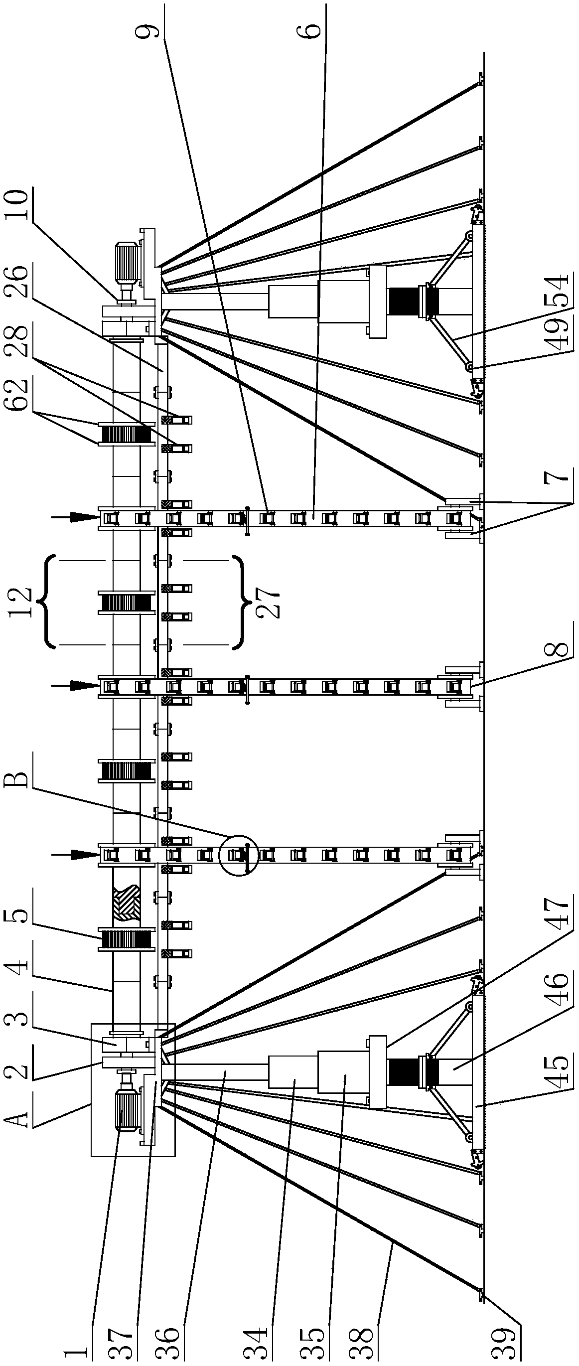
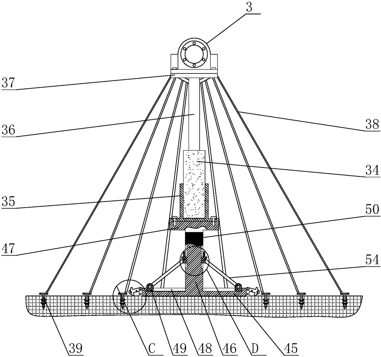
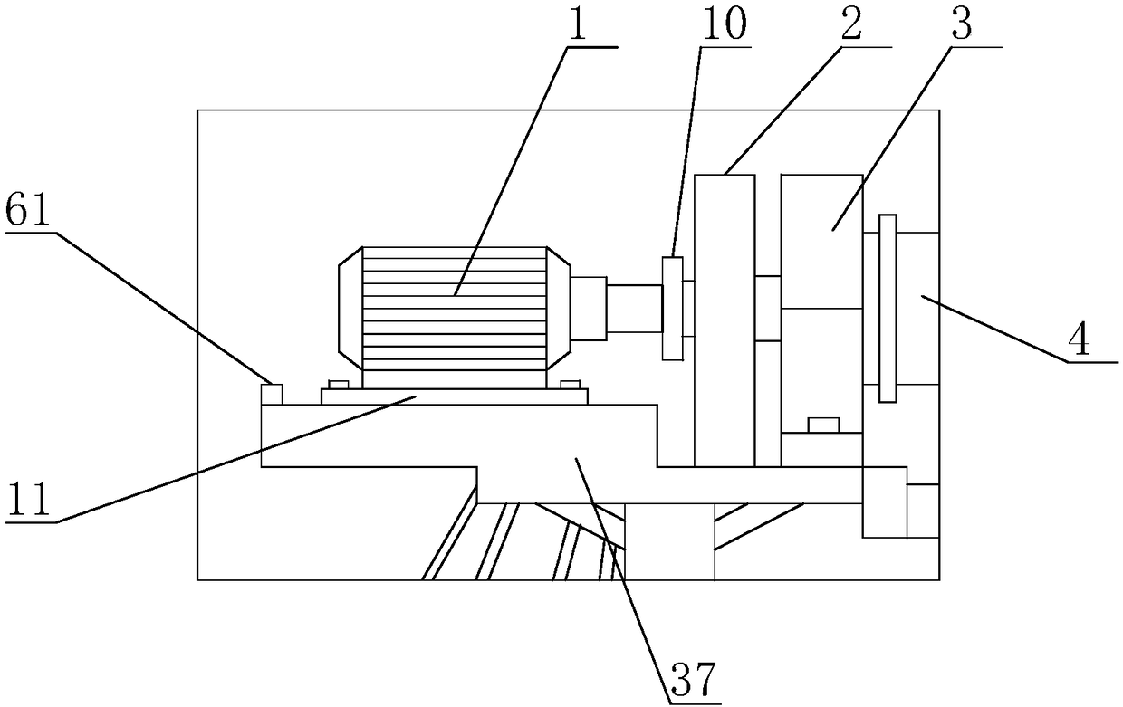
[0048] As attached to the manual figure 1 As shown, the present invention is a construction material conveying device. The main structure includes two adjustable support frames, a driving mechanism and a material conveying mechanism. The driving mechanism includes a driving motor 1, a reducer 2, a top bearing seat 3 and Drive the main shaft 4, the driving motor 1, the reducer 2, and the top bearing seat 3 are arranged on the top of the adjustable support frame, the driving motor 1 is connected with the driving main shaft 4 through the speed reducer 2, and the driving main shaft 4 is provided with There are several driving gears 5, seven of which are provided in this embodiment; the material conveying mechanism includes a transmission toothed belt 6, a bottom bearing seat 7 and a driven gear 8 arranged on the ground, and the transmission toothed belt 6 is tightly arranged on Between the driving gear 5 and the driven gear 8 , the rotating shafts at both ends of the driven gear 8...


PUM


Abstract

The invention discloses a construction material conveying apparatus, and mainly relates to the field of construction equipment. The construction material conveying apparatus comprises two adjustable support frames, a driving mechanism, and a material conveying mechanism. The driving mechanism comprises a driving motor, a decelerator, a top bearing pedestal, and a driving main shaft. A driving gearis arranged on the driving main shaft. The material conveying mechanism comprises a conveying toothed belt, a bottom bearing pedestal arranged on the ground, and a driven gear. The conveying toothedbelt is tightened and is arranged between the driving gear and the driven gear. The rotation shafts of two ends of the driven gear are arranged on the bottom bearing pedestal. The external surface ofthe conveying toothed belt is provided with a plurality of material hanging devices. The conveying apparatus is suitable for transporting construction materials in a low building, is convenient to operate and control, can convey construction materials automatically and mechanically, and is capable of delivering materials to construction workers in all positions; the construction efficiency is largely improved, the labor cost is reduced, and furthermore, the conveying apparatus is convenient to assemble, disassemble, and transport, and promotes the development of construction in rural areas.

Description

technical field [0001] The invention relates to the field of construction equipment, in particular to a construction material conveying device. Background technique [0002] With the improvement of people's living standards, people's clothing, food, housing, and transportation have been greatly improved compared with the past. Low-rise small buildings such as two-story small buildings and three-story small buildings in rural areas are becoming more and more popular. In the past, some construction equipment was mostly suitable for the construction of old-fashioned houses. When building small buildings such as two-story buildings and three-story buildings, it is difficult for some existing construction equipment to meet the requirements for building use. When building low-rise buildings by means of manual transportation and other methods, mechanization and automatic transportation of materials cannot be realized, which not only greatly increases construction costs such as labo...

Claims


Application Information

Patent Timeline
IPC IPC(8): B66C11/16B66C5/02B66C1/18
CPCB66C1/18B66C5/02B66C11/16
Inventor 岳晓楠
Owner 岳晓楠
Why Eureka
Try Eureka