
Environment-friendly non-stick pan surface treatment process

A surface treatment, non-stick pan technology, applied in the direction of manufacturing tools, metal processing equipment, the structure of cooking utensils, etc., can solve problems such as insufficient environmental protection, coating peeling, increase production costs, etc., to save production costs and improve adhesion , the effect of increasing the surface area

Active Publication Date: 2018-07-24
ZHEJIANG SANHO KITCHENWARE
View PDF8 Cites 4 Cited by
  • Summary
  • Abstract
  • Description
  • Claims
  • Application Information

AI Technical Summary

Problems solved by technology

[0003] Both sandblasting and shot blasting increase the roughness of the surface of the pan by deforming the surface of the pan. Figure 4 It is a partial cross-sectional schematic diagram of a non-stick pan after sandblasting (non-stick coating is not shown), Figure 5 It is a partial cross-sectional schematic diagram of a non-stick pan after shot blasting (non-stick coating is not shown), from Figure 4 and Figure 5 It can be seen from the figure that although the surface of the pan has obvious concave and convex parts under the action of deformation, if the non-stick coating is directly sprayed on the surface of the pan, the adhesion between the non-stick coating and the surface of the pan will The force is not enough to ensure that the coating is firmly attached to the surface of the pan, and the coating is easy to fall off from the surface of the pan under the impact of hard objects. Therefore, before spraying the non-stick coating, a layer of base oil or Medium oil is used to improve the adhesion of the non-stick coating, but this not only increases the production cost, but is not environmentally friendly enough

Method used

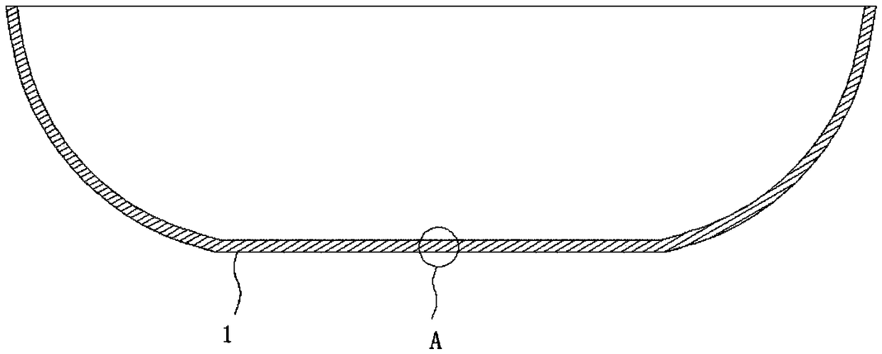

Image

  • Environment-friendly non-stick pan surface treatment process
  • Environment-friendly non-stick pan surface treatment process
  • Environment-friendly non-stick pan surface treatment process

Examples


Embodiment Construction

[0029] In order to enable those skilled in the art to better understand the solutions of the present invention, the technical solutions in the embodiments of the present invention will be described clearly and completely in conjunction with the accompanying drawings in the embodiments of the present invention.

[0030] An environmentally friendly surface treatment process for non-stick pans, including the following steps:

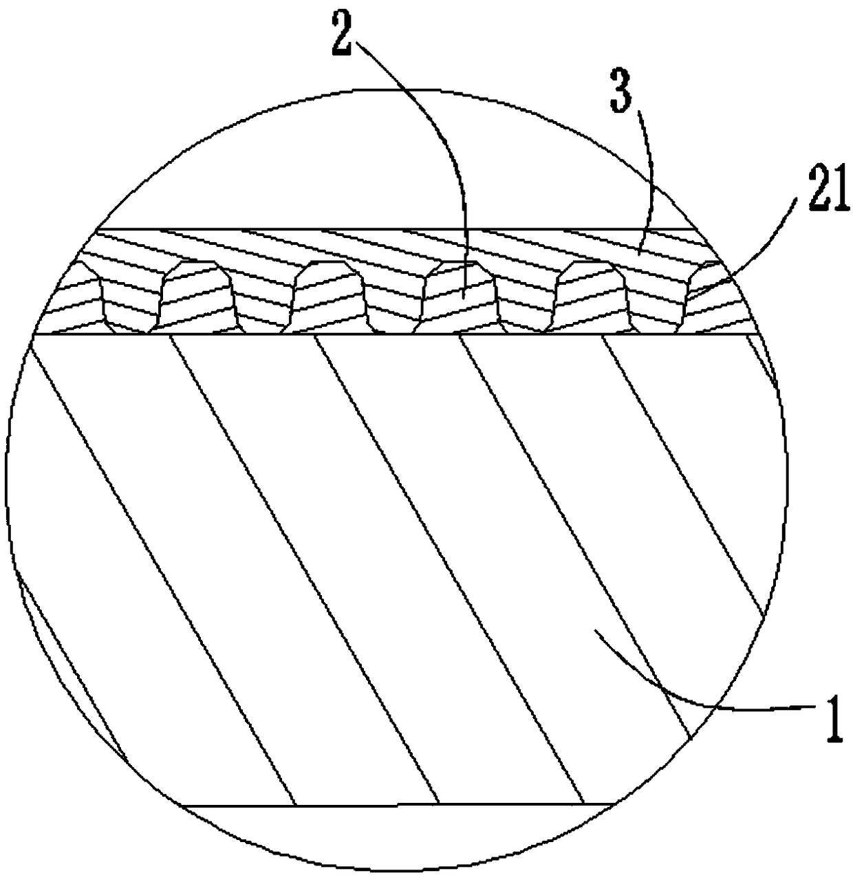
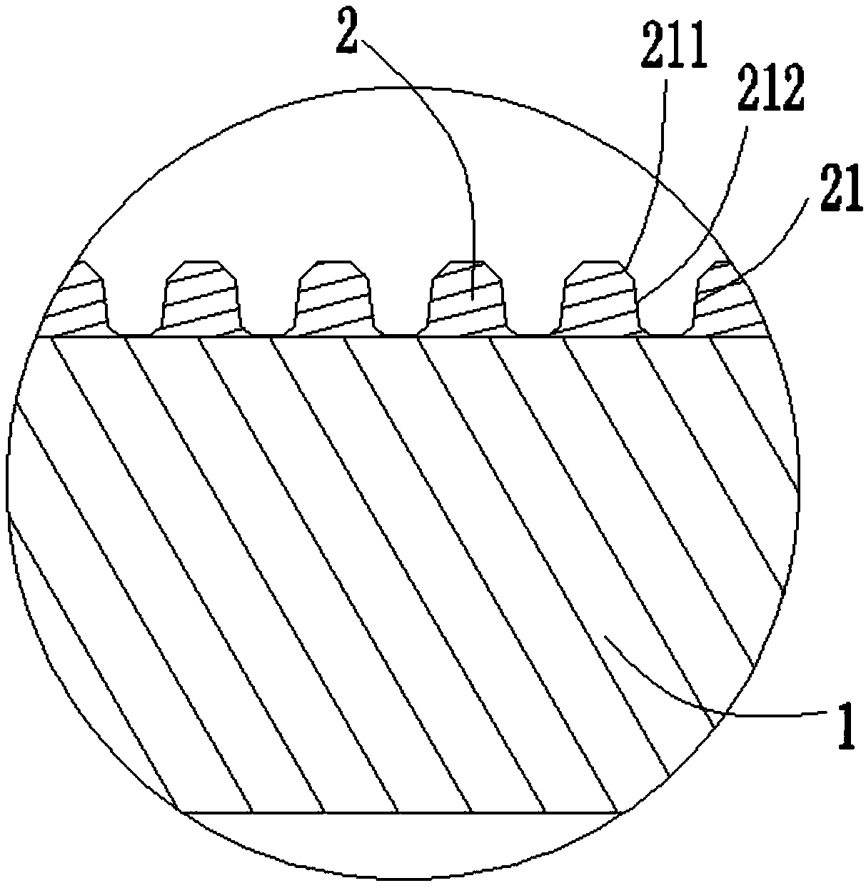
[0031] 1) Pot blank forming: 2) Forming microporous layer: using laser scanning to form multiple microporous structures on the surface of the pot blank, thereby forming the microporous layer; 3) Spraying a non-stick coating on the surface of the microporous layer: the The non-stick coating is filled in the microporous structure. Due to the use of a laser in the present invention, a microporous structure can be produced on the surface of the pot embryo. These microporous structures can achieve a small diameter and a long hole depth. The micropores of these slende...


PUM

PropertyMeasurementUnit
Hole depthaaaaaaaaaa
Apertureaaaaaaaaaa
Wavelengthaaaaaaaaaa

Abstract

The invention discloses an environment-friendly non-stick pan surface treatment process. The treatment process comprises the following steps of 1), molding to form a microporous layer; 2), using a laser for scanning on the surface of a pan blank to form a plurality of microporous structures to obtain the microporous layer; 3), spraying a non-stick coating on the surface of the microporous layer, wherein the microporous structures are filled with the non-stick coating. The treatment process adopts a laser micro-porous forming technology for scanning the surface of the pan blank to form the dense and slender microporous structures to obtain the microporous layer, so that the superficial area of the pan blank is increased by folds, the microscopic roughness of the surface of the pan blank isimproved, when the non-stick coating is directly sprayed on the surface of the microporous layer, the microporous structures are filled with the coating to greatly increase the contact area between the non-stick coating and the microporous layer to improve the adhesion of the non-stick coating.

Description

Technical field [0001] The invention belongs to the technical field of cookware manufacturing, and particularly relates to an environmentally-friendly non-stick pan surface treatment process. Background technique [0002] At present, spraying pot blanks in the pot industry basically use surface sandblasting or shot blasting to increase the surface roughness of the pot blanks to improve the adhesion of the surface non-stick coating. [0003] Sandblasting and shot blasting both increase the surface roughness of the pot body by deforming the surface of the pot body. Figure 4 Is a partial cross-sectional schematic diagram of a non-stick pan after sandblasting (non-stick coating is not shown), Figure 5 The partial cross-sectional schematic diagram of the non-stick pan after shot blasting (non-stick coating is not shown), from Figure 4 with Figure 5 It can be seen that although the surface of the pot blank has obvious concave and convex parts under the action of deformation, if the non-...

Claims


Application Information

Patent Timeline
IPC IPC(8): A47J27/00A47J36/02B23K26/382
CPCA47J27/002A47J36/025B23K26/382
Inventor 方成陶列刚
Owner ZHEJIANG SANHO KITCHENWARE
Learn More