Tube bender

A technology of pipe bending device and splint, which is used in feeding device, positioning device, stripping device, etc., can solve the problems of poor steel pipe clamping and easy movement of steel pipe, so as to avoid inaccurate bending size, less power mechanism, etc. Low energy consumption

Active Publication Date: 2019-07-02
CHONGQING JIANAN IND & TRADE
View PDF8 Cites 0 Cited by
  • Summary
  • Abstract
  • Description
  • Claims
  • Application Information

AI Technical Summary

Problems solved by technology

[0006] The purpose of the present invention is to provide a pipe bending device to solve the problem that the steel pipe is easy to move during the pipe bending process and the steel pipe is not well clamped

Method used


Image

  • Tube bender
  • Tube bender
  • Tube bender

Examples


Embodiment Construction

[0021] The present invention will be described in further detail below by means of specific embodiments:

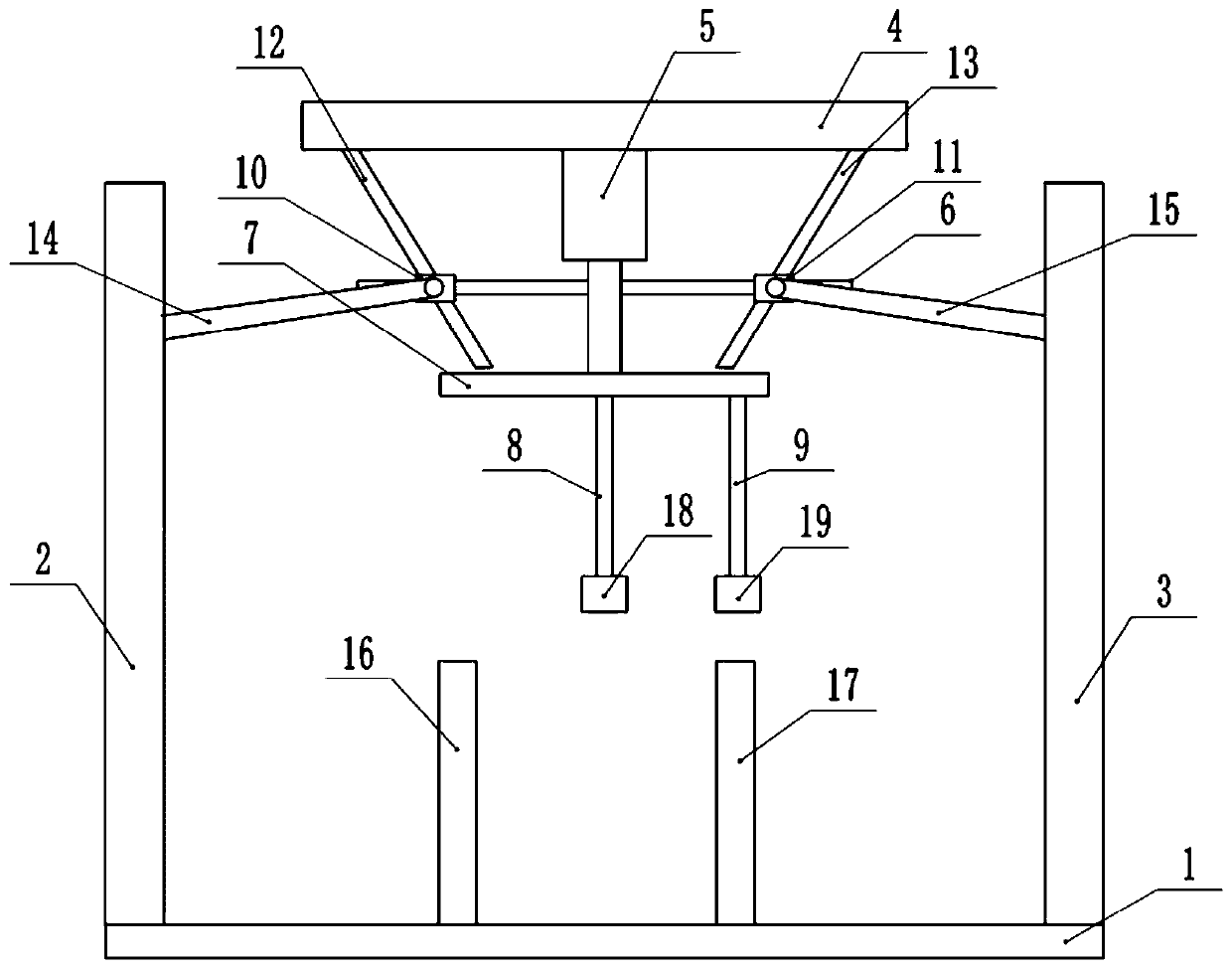
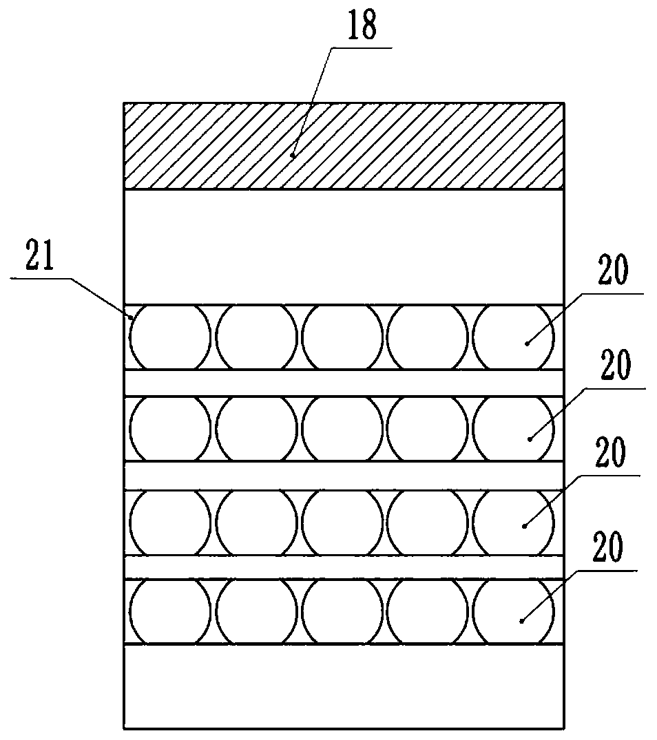
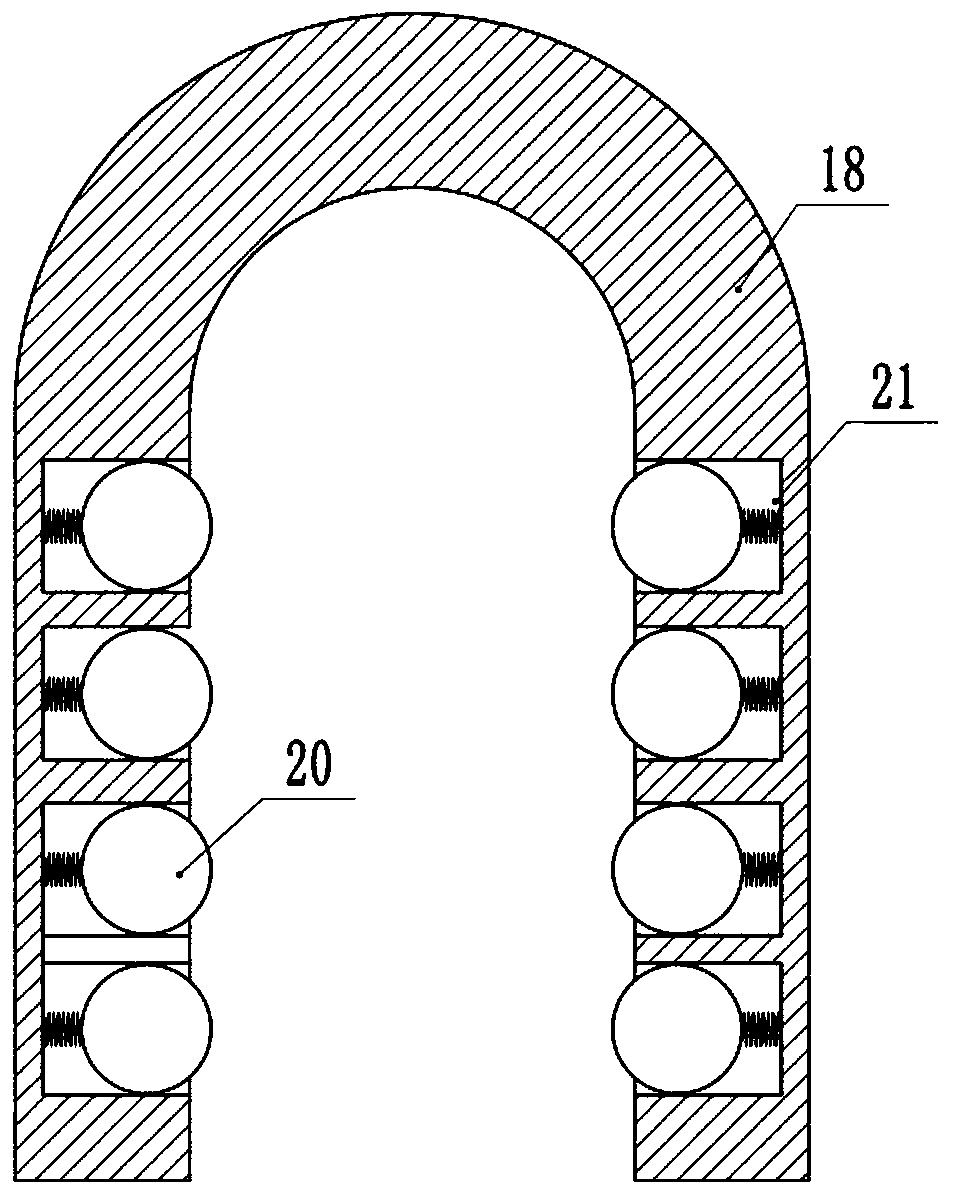
[0022] The reference signs in the drawings of the description include: base 1, first splint 2, second splint 3, crossbeam 4, cylinder 5, crossbar 6, crossplate 7, first compression rod 8, second compression rod 9, first compression rod One slide block 10, the second slide block 11, the first oblique bar 12, the second oblique bar 13, the first connecting rod 14, the second connecting rod 15, the first support rod 16, the second support rod 17, the first buckle Groove 18, second buckle groove 19, ball 20, through groove 21.

[0023] Such as figure 1 As shown, the pipe bending device includes a base 1, a first splint 2, a second splint 3 and a column, a slide rail is installed on the base 1, rollers are installed on the lower ends of the first splint 2 and the second splint 3, the first splint 2 and The second clamping plate 3 is installed in the slide rail by rollers; th...


PUM


Abstract

The invention belongs to the technical field of pipe bending equipment, and particularly discloses a pipe bending device. The pipe bending device comprises a base, a first clamping plate, a second clamping plate, a stand column, a first supporting rod and a second supporting rod are arranged on the base, a transverse beam is arranged on the stand column and is provided with an air cylinder, a first inclined rod and a second inclined rod, a transverse plate and a transverse rod are arranged on a piston rod, a first pressing rod is arranged on the transverse plate, the two ends of the transverserod are provided with a first sliding block and a second sliding block which are in sliding connection with the transverse rod, and the first sliding block and the second sliding block are in slidingconnection with the first inclined rod and the second inclined rod correspondingly; and a first connecting rod and a second connecting rod are hinged to the first sliding block and the second slidingblock correspondingly, the end, far away from the first sliding block, of the first connecting rod is hinged to the first clamping plate, and the end, far away from the second sliding block, of the second connecting rod is hinged to the second clamping plate. The pipe bending device is mainly used for bending a steel pipe, and the problem that pipe clamping is not good in the pipe bending processis solved.

Description

technical field [0001] The invention belongs to the technical field of pipe bending equipment, and specifically discloses a pipe bending device. Background technique [0002] Due to the hollow structure of the steel pipe, the steel pipe is widely used in heat exchangers and heaters. Since the inner surface and the outer surface of the steel pipe have a larger area, the steel pipe has a better heat transfer effect in the heat conduction process. [0003] When the steel pipe is used as a heating pipe, the requirements for the shape of the heating pipe are also different due to the different occasions and materials to be used for the heating pipe. The heating pipe used in some occasions requires the shape of the heating pipe to be a straight pipe, and some occasions require the use of For curved steel pipes, the current method of processing the heating pipe into a bent pipe is manual processing, or manual processing with some simple tools, so that the shape of the processed hea...

Claims


Application Information

Patent Timeline
Patent Type & Authority Patents(China)
IPC IPC(8): B21D7/06B21D43/00B21D45/10
CPCB21D7/06B21D43/003B21D45/10
Inventor 肖福禄
Owner CHONGQING JIANAN IND & TRADE
Why Eureka
Try Eureka