
Method and system for controlling cooling system of power equipment

A technology for power equipment and cooling systems, applied in general control systems, control/regulation systems, transformer/inductor cooling, etc., can solve the problem of high initial temperature and insufficient quantitative models to meet the operating efficiency goals of power equipment, Increase transformer power loss and life loss and other issues

Active Publication Date: 2018-07-17
HITACHI ENERGY LTD
View PDF2 Cites 2 Cited by
  • Summary
  • Abstract
  • Description
  • Claims
  • Application Information

AI Technical Summary

Problems solved by technology

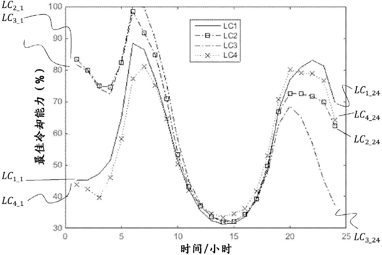
However, since the magnitude of the response related to previous time intervals will have an impact on subsequent time intervals, a quantitative model-based optimization design alone may not be sufficient to meet the best criteria for operating efficiency targets for the load cycle of a power plant
For example, cooling optimization at time interval n may result in a higher initial temperature at time interval n+1
In terms of calculating the response quantities for time intervals involving load cycles after the initial time interval n, this temperature difference will gradually add up, which will gradually increase the power loss and life loss of the transformer
So even if the optimization algorithm according to each time interval can achieve the best result in each time interval, it is not necessarily optimal for the whole load cycle

Method used


Image

  • Method and system for controlling cooling system of power equipment
  • Method and system for controlling cooling system of power equipment
  • Method and system for controlling cooling system of power equipment

Examples


Embodiment Construction

[0021] In the following description, for purposes of explanation and not limitation, specific details such as particular circuits, circuit components, interfaces, techniques, etc. are set forth in order to provide a thorough understanding of the present invention. It will be apparent, however, to one skilled in the art that the invention may be practiced in other embodiments without these specific details. In other instances, detailed descriptions of well-known methods, programs, devices, and circuits are omitted so as not to obscure the description of the present invention with unnecessary detail.

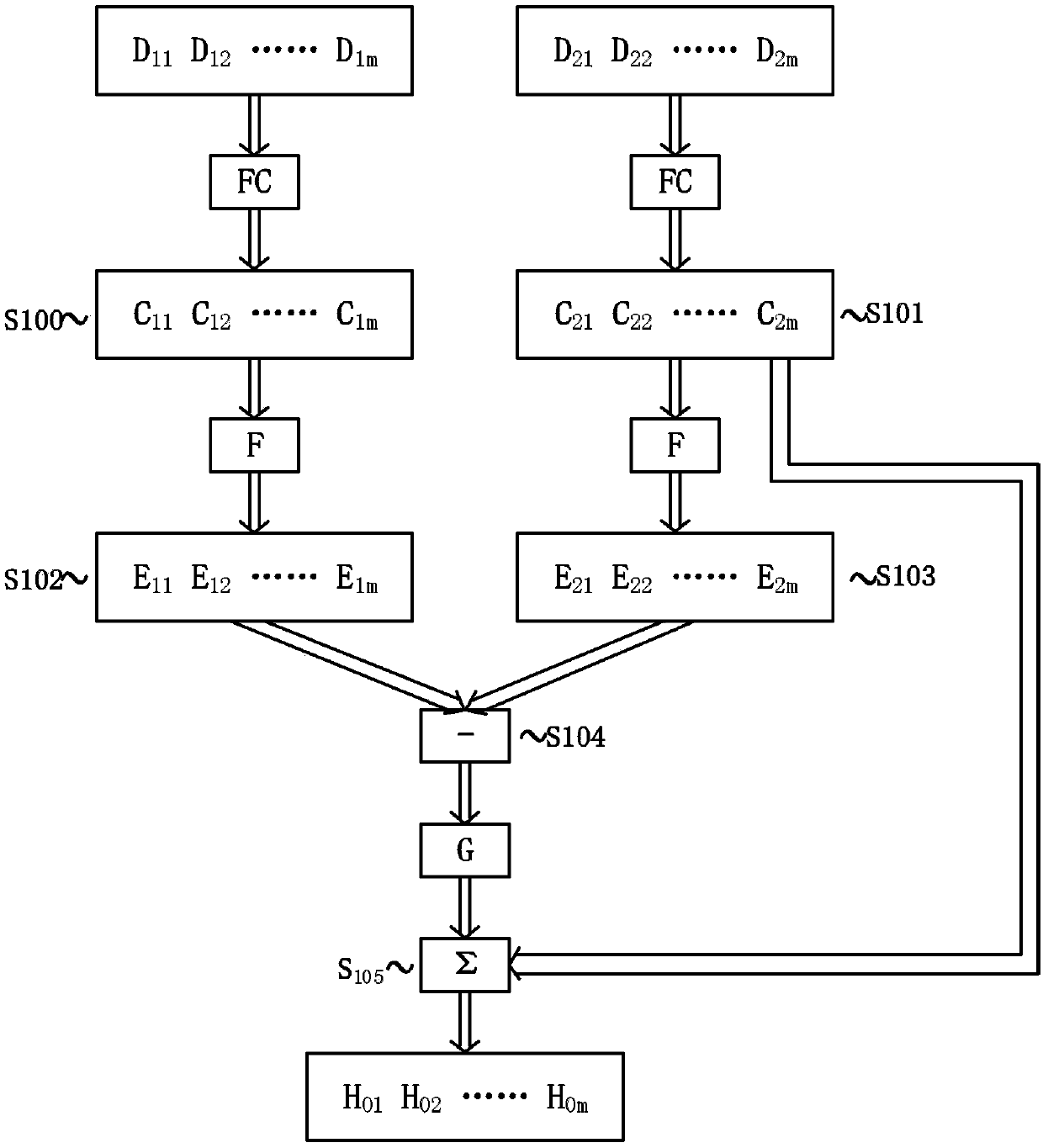
[0022] figure 1 A method for controlling a cooling system of an electric device according to an embodiment of the present invention is illustrated. For example, the electrical device is a power transformer. Such as figure 1 As shown in , step by step determine the operating cost-related parameters Powerloss, Lifeloss, and Noisereductionloss of the first load cycle and the secon...


PUM


Abstract

It provides a method for controlling cooling system of a power equipment and a system using the same. The method includes steps of: obtaining a first data set representing operational cost related parameters specific to the power equipment and its cooling system at a series of time intervals of a first load cycle in a history profile; obtaining a second data set representing operational cost related parameters specific to the power equipment and its cooling system at a series of time intervals of a second load cycle in the history profile, where the second load cycle follows the first load cycle; in consideration of the parameters represented by the first data set, through knowledge-based predetermined numerical and / or logical linkages, establishing a third data set representing optimal cooling capacity parameters for the cooling system at the series of time intervals of the first load cycle according to criteria for operational cost optimization of the power equipment; in consideration of the parameters represented by the second data set, through knowledge-based predetermined numerical and / or logical linkages, establishing a fourth data set representing optimal cooling capacity parameters for the cooling system at the series of time intervals of the second load cycle according to criteria for operational cost optimization of the power equipment; establishing a fifth data set representing a cooling capacity parameter difference between the established cooling capacity parameters concerning the first load cycle and the second load cycle; establishing a sixth data set representing cooling capacity parameters for the cooling system at a series of time intervals of a present load cycle by computationally correcting the established cooling capacity parameter concerning the time intervals of the second cycle load with use of the cooling capacity parameter difference; and controlling the cooling system to operate at a series of time intervals of the present load cycle at the established cooling capacity parameters concerning the present load cycle represented by the sixth data set.

Description

technical field [0001] The present invention relates to temperature control of electrical equipment, and more particularly to controlling the temperature of electrical equipment through digital data processing. Background technique [0002] For example, electrical equipment can be power transformers, motors, etc., whose losses vary with their load level, and most of their losses are converted to heat. Due to the high power ratings, electrical equipment is typically cooled by forced air cooling, forced oil cooling, water cooling, or a combination of these. Therefore, electrical equipment requires a cooling system, which may for example be arranged with at least one fan or blower to pump cooling air or a liquid coolant such as oil and water. It is common practice to slow down or speed up cooling systems to keep the temperature of electrical equipment within a predetermined range, and there are many techniques to achieve this. [0003] The operating efficiency of electrical e...

Claims


Application Information

Patent Timeline
Patent Type & Authority Applications(China)
IPC IPC(8): H01F27/08
CPCH01F27/08G06Q50/06G06F1/20G06F1/206Y02D10/00G05B19/408H01F27/008H01F27/085H01F27/33H05K7/20209
Inventor 陈瑶陈妮亚于蓉蓉
Owner HITACHI ENERGY LTD
Learn More