Online measuring device and measuring method for cage end flanges

A measuring device and cage technology, applied in the direction of measuring devices, mechanical measuring devices, mechanical devices, etc., can solve the problems of inability to realize online measurement, reduce production efficiency, and fail to see, so as to achieve fast and convenient online measurement and improve production efficiency effect

Active Publication Date: 2018-07-17
LUOYANG BEARING RES INST CO LTD
View PDF4 Cites 4 Cited by
  • Summary
  • Abstract
  • Description
  • Claims
  • Application Information

AI Technical Summary

Problems solved by technology

These two technical requirements determine that the cage cannot be directly clamped and ground on the surface grinding machine, and the grinding device must be designed to ensure that although the H dimension can be measured with a three-coordinate measuring instrument, it cannot be measured online, and repeated disassembly, measurement, Re-clamping not only affects the machining accuracy of the H dimension of the cage, but also reduces production efficiency. Therefore, a fast and convenient online measurement method must be designed
[0003] An on-line measuring device for the flange of the end face of the cage and the measuring method realized by using the device have not yet seen related reports

Method used


Image

  • Online measuring device and measuring method for cage end flanges
  • Online measuring device and measuring method for cage end flanges
  • Online measuring device and measuring method for cage end flanges

Examples


Embodiment Construction

[0032] In order to facilitate the understanding of the technical means, creative features and goals achieved by the present invention, the present invention is further described below in conjunction with the schematic diagrams, but the scope of protection claimed by the present invention is not limited to the scope described in the specific implementation.

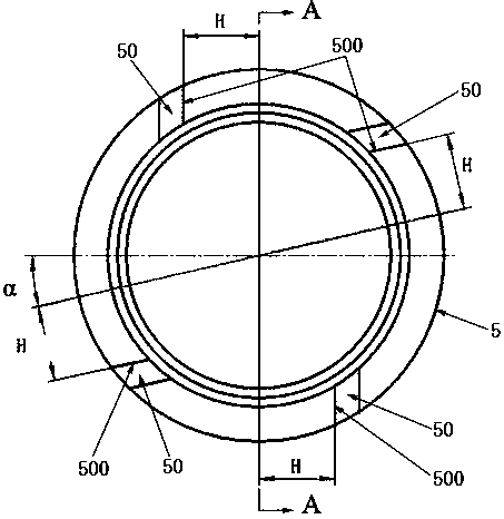
[0033] The structure of the cage is as figure 1 and figure 2 As shown, wherein, several windows 51 are evenly divided on the cage 5, preferably, the number of windows 51 is 14 or 16; as figure 1 As shown, one end of the cage 5 is provided with four flanges 50, wherein two flanges arranged at intervals are arranged parallel to the vertical center line of the cage 5, and the adjacently arranged side surfaces of the two flanges are the processing surfaces. The distance between the 500 and the vertical center line of the cage 5 is H; the other two spaced flanges are arranged in parallel, and the adjacent sides of the two fla...


PUM


Abstract

An online measuring device and a measuring method for cage end flanges are provided. The device comprises a clamping tool and a measuring tool. The clamping tool comprises a base plate, a positioningplate, a long cylindrical pin and pressing plates. The pressing plates are installed on the base plate. The positioning plate is arranged in a window hole of a cage in a penetrating manner. The long cylindrical pin is fixed on the base plate, and abuts against the wall of the positioning plate. The measuring tool comprises a pressing ring, a measuring plate, short cylindrical pins and two cylindrical rollers. The short cylindrical pins are vertically connected with one end of the positioning plate. The two cylindrical rollers are arranged on the short cylindrical pins in a penetrating manner.The measuring plate vertically sleeves the positioning plate. The length of the measuring plate is the same with the maximum outer diameter of the cage. The pressing ring abuts against the outer sideof the measuring plate, and is tightly pressed on the outer side of the measuring plate by a screw I connected with one end of the positioning plate. The problem that online grinding and measuring cannot be realized by a surface grinder is solved. The purpose of fast and convenient online measurement is achieved. The production efficiency is improved.

Description

technical field [0001] The invention relates to the technical field of mechanical manufacturing, in particular to an on-line measuring device and a measuring method for an end face flange of a cage. Background technique [0002] There are several window holes on the circumference of the cage, and several equal flanges on the end face of the cage. Generally, four equal flanges are provided on the end face of the cage, such as figure 1 As shown, the distance dimension H between the flange and the radial line passing through the center of the cage can be as small as 20.4mm; at the same time, the angular position of the flange on the end face of the cage and the window hole of the cage has positional requirements. These two technical requirements determine that the cage cannot be directly clamped and ground on the surface grinding machine, and the grinding device must be designed to ensure that although the H dimension can be measured with a three-coordinate measuring instrument...

Claims


Application Information

Patent Timeline
Patent Type & Authority Applications(China)
IPC IPC(8): G01B5/06
CPCG01B5/061
Inventor 张黎阳徐浩李泽强高海潮李慎华马延波
Owner LUOYANG BEARING RES INST CO LTD
Why Eureka
Try Eureka