Eureka AIR delivers breakthrough ideas for toughest innovation challenges, trusted by R&D personnel around the world.

A livestock feed screening device

A feed sieving and sieving technology, which is applied in the fields of sieving, solid separation, chemical instruments and methods, etc., can solve the problems of automatic sieving of feed, inability to reuse, low work efficiency, etc., and achieve novel and practical design Strong, well-structured effect

Active Publication Date: 2022-08-02
诸城市中裕机电设备有限公司
View PDF4 Cites 0 Cited by
  • Summary
  • Abstract
  • Description
  • Claims
  • Application Information

AI Technical Summary

Problems solved by technology

[0003] However, the existing screening device does not have the function of automatically screening the feed, which is more labor-intensive and has low work efficiency. At the same time, after screening, the feed with larger particles will be screened out and cannot be reused, which is a waste of feed. Therefore, needs further improvement

Method used


Image

  • A livestock feed screening device
  • A livestock feed screening device
  • A livestock feed screening device

Examples


Embodiment 1

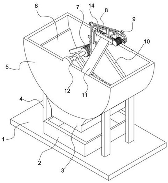
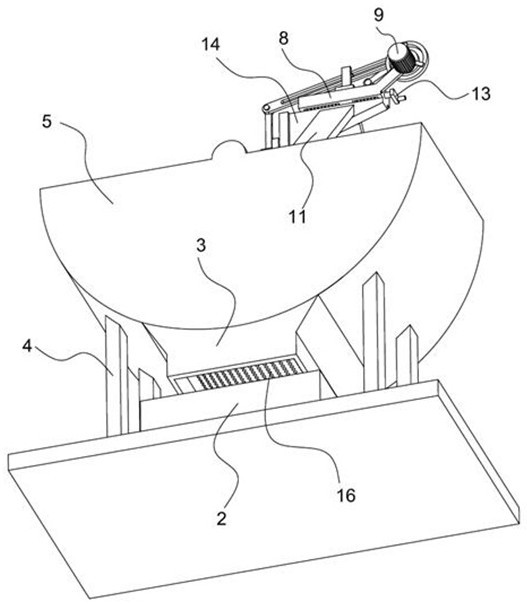
[0032] see Figures 1 to 9 , In the embodiment of the present invention, a livestock feed screening device includes a fixed base 1, and a screening box 5 is installed on the upper side of the fixed base 1 through a support column 4, thereby ensuring the stable support and installation of the screening box 5, and the screen The screening shaft 12 is rotated and installed on the upper side of the sub-box 5. The screening gear 7 is installed in the middle of the screening shaft 12. The screening shaft 12 and the screening gear 7 are fixedly connected by keys. The connecting frame 10 is fixedly installed at the side position, and the bottom of the connecting frame 10 is installed with the screening plate 6 close to the inner bottom side of the screening box 5. For effective grinding and screening, a limit plate 14 is installed on the upper side of the screening box 5 through the limit frame 11, and a power mechanism for driving the screening shaft 12 to reciprocate is installed on...

Embodiment 2

[0039] In another embodiment of the present invention, the difference between this embodiment and the above-mentioned embodiment lies in that, one end of the lead screw 28 is installed with the handle 13 through the limit frame 8, which facilitates the staff to adjust the lead screw 28 Rotation is performed to further improve the reliability of the device.

[0040] The working principle of the present invention is: when working, the feed that needs to be screened is placed on the screening plate 6 inside the screening box 5, the larger particles will stay on the upper side of the screening plate 6, and the smaller particles of feed It will be introduced into the position between the bottom of the screening plate 6 and the bottom of the screening box 5 through the screening hole 17, and then start the power motor 9, so that the screening plate 6 swings back and forth inside the screening box 5, and then the feed is carried out. Grinding and squeezing, and finally discharge the ...


PUM


Abstract

The invention relates to the technical field of feed processing equipment, and discloses a livestock feed screening device. The screening gear is installed in the middle position, the connecting frame is fixedly installed on the front and rear sides of the screening shaft, the screening plate close to the inner bottom side of the screening box is installed at the bottom of the connecting frame, and the limit plate is installed on the upper side of the screening box through the limit frame The limit plate is installed with a power mechanism that drives the reciprocating rotation of the screening shaft. The power mechanism includes a lift assembly and a drive assembly that drives the movement of the lift assembly. An adjustment assembly for adjusting the reciprocating depth of the lift assembly is also installed between the drive assembly and the lift assembly. The invention not only realizes the sieving of the feed, but also ensures the grinding of the feed with larger particles, and avoids the effective waste of the feed. the screening efficiency.

Description

technical field [0001] The invention relates to the technical field of feed processing equipment, in particular to a livestock feed screening device. Background technique [0002] Feed is a general term for the food of animals raised by all people. In a narrower sense, general feed mainly refers to the food of animals raised in agriculture or animal husbandry. Feed includes soybeans, soybean meal, corn, fish meal, amino acids, miscellaneous meal, additives, milk. There are more than ten varieties of feed raw materials such as clear powder, oil, meat and bone meal, grain, sweet sorghum, etc. The existing feed needs to be sieved before eating, and the high-quality feed at the sieved place is used for animal husbandry, so that it can grow healthily. [0003] However, the existing screening device does not have the function of automatically screening the feed, which is labor-intensive and low in work efficiency. At the same time, after screening, larger particles of feed will be...

Claims


Application Information

Patent Timeline
Patent Type & Authority Patents(China)
IPC IPC(8): B07B1/28B07B1/42B07B1/46
CPCB07B1/28B07B1/42B07B1/46
Inventor 刘红光廖俊涛李湖波臧运强李朋朋张茂兵
Owner 诸城市中裕机电设备有限公司
Why Eureka
Eureka Blog
Learn More