A chemical laboratory grinding device

A chemical laboratory and grinding device technology, applied in grain processing and other directions, can solve the problems of shortening the service life of the grinding mechanism, clogging of the grinding machine, collapse of the crushing blade, etc., to ensure the normal grinding, improve the service life, and achieve the effect of uniform crushing.

Active Publication Date: 2021-06-15
济南工程职业技术学院
View PDF0 Cites 0 Cited by
  • Summary
  • Abstract
  • Description
  • Claims
  • Application Information

AI Technical Summary

Problems solved by technology

[0002] The chemical laboratory is an important place to provide chemical experiment conditions and conduct scientific research. There are a large number of instruments, including some mechanical instruments. These instruments are mainly used for pretreatment of experimental raw materials, among which grinding equipment is essential. , some chemical experiments need to dissolve solids, which requires crushing and grinding large-grained solid raw materials first, so as to facilitate dissolution. Existing grinding equipment often directly puts particles into grinding, which often causes grinding machinery If you want to avoid this kind of situation, you need to pre-grind manually. Most of the grinding devices are mechanically crushed. Some experimental medicines are hard and have large particles. If they are directly crushed, the crushing blade may be broken. , causing unnecessary economic losses. Most of the existing grinding devices are driven by the motor to move the grinding mechanism. Once there is a problem with the motor, the grinding process cannot be carried out, which greatly affects the progress of the experiment. Most of the chemicals are corrosive. Finally, some chemicals stick to the grinding mechanism. If it is not treated in time, it will corrode the grinding mechanism in the long run and greatly shorten the service life of the grinding mechanism.

Method used


Image

  • A chemical laboratory grinding device
  • A chemical laboratory grinding device
  • A chemical laboratory grinding device

Examples


Embodiment Construction

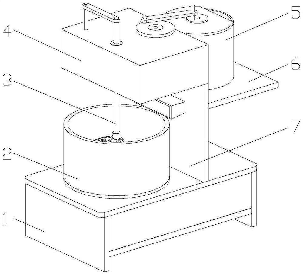
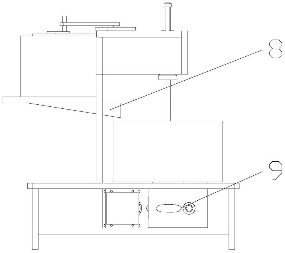
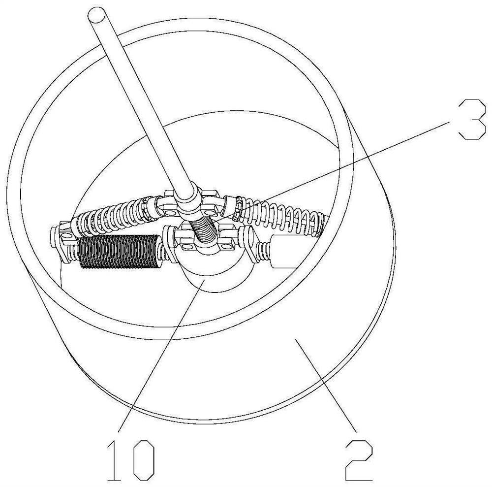
[0033] Attached below Figure 1-13 , clearly and completely describe the technical solutions in the embodiments of the present invention, obviously, the described embodiments are only some of the embodiments of the present invention, not all of them. Based on the embodiments of the present invention, all other embodiments obtained by persons of ordinary skill in the art without making creative efforts belong to the protection scope of the present invention.

[0034] In describing the present invention, it should be understood that the terms "longitudinal", "transverse", "upper", "lower", "front", "rear", "left", "right", "vertical", The orientations or positional relationships indicated by "horizontal", "top", "bottom", "inner", "outer", etc. are based on the orientations or positional relationships shown in the drawings, and are only for the convenience of describing the present invention, rather than indicating or It should not be construed as limiting the invention by impl...


PUM


Abstract

The invention discloses a grinding device for a chemical laboratory, which comprises a base, a grinding tank and a vertical plate are arranged on the top of the base, a grinding mechanism and a fixing table are arranged inside the grinding tank, and the fixing table is installed on the grinding tank. The bottom of the tank, the bottom of the grinding mechanism is installed on the fixed table. The crushing mechanism of the present invention can carry out preliminary crushing treatment on chemicals, and crush the agglomerated chemicals through the rotation of the crushing blade, and the lifting mechanism can drive the grinding mechanism to lift through the action of the pneumatic cylinder, which is convenient for cleaning the device. The service life of the device is improved, the transmission mechanism can drive the grinding tank to move, prevent the second motor failure, the device cannot work, and improve the efficiency of the experiment. The crushing blade on the first grinding wheel in the grinding mechanism can crush and grind chemicals. The second grinding wheel grinds the chemicals again, not only will not break the crushing blade, but also the crushing is more uniform.

Description

technical field [0001] The invention belongs to the technical field of chemical experiments, in particular to a grinding device for chemical laboratories. Background technique [0002] The chemical laboratory is an important place to provide chemical experiment conditions and conduct scientific research. There are a large number of instruments, including some mechanical instruments. These instruments are mainly used for pretreatment of experimental raw materials, among which grinding equipment is essential. , some chemical experiments need to dissolve solids, which requires crushing and grinding large-grained solid raw materials first, so as to facilitate dissolution. Existing grinding equipment often directly puts particles into grinding, which often causes grinding machinery If you want to avoid this kind of situation, you need to pre-grind manually. Most of the grinding devices are mechanically crushed. Some experimental medicines are hard and have large particles. If the...

Claims


Application Information

Patent Timeline
Patent Type & Authority Patents(China)
IPC IPC(8): B02C21/00B02C18/10B02C18/24B02C15/08
CPCB02C15/08B02C18/10B02C18/24B02C21/00B02C2015/008
Inventor 路静
Owner 济南工程职业技术学院
Why Eureka
Try Eureka