Magnetic valve for a fuel injection system and high pressure fuel pump

A technology of fuel injection system and solenoid valve, applied in the direction of fuel injection pump, fuel injection device, charging system, etc., which can solve the problems of solid sound undesired emission, material wear and so on

Inactive Publication Date: 2018-07-17
CONTINENTAL AUTOMOTIVE GMBH
View PDF6 Cites 0 Cited by
  • Summary
  • Abstract
  • Description
  • Claims
  • Application Information

AI Technical Summary

Problems solved by technology

Depending on the momentum directly linked to the mass of the armature through the velocity, mechanical vibrations occur when the armature strikes, which on the one hand lead to material wear, but on the other hand also lead to undesired emissions of solid-state sounds

Method used


Image

  • Magnetic valve for a fuel injection system and high pressure fuel pump
  • Magnetic valve for a fuel injection system and high pressure fuel pump
  • Magnetic valve for a fuel injection system and high pressure fuel pump

Examples


Embodiment Construction

[0038] figure 1A schematic overview of a fuel injection system 10 of an internal combustion engine is shown, which delivers fuel 12 from a fuel tank 14 to injectors 22 via a prefeed pump 16 , a high-pressure fuel pump 18 and a high-pressure fuel accumulator 20 , The injector then injects fuel 12 into the combustion chamber of the internal combustion engine.

[0039] Fuel 12 is introduced into high-pressure fuel pump 18 via inlet valve 24 , is discharged under pressure from high-pressure fuel pump 18 via outlet valve 26 , and is delivered to high-pressure fuel accumulator 20 .

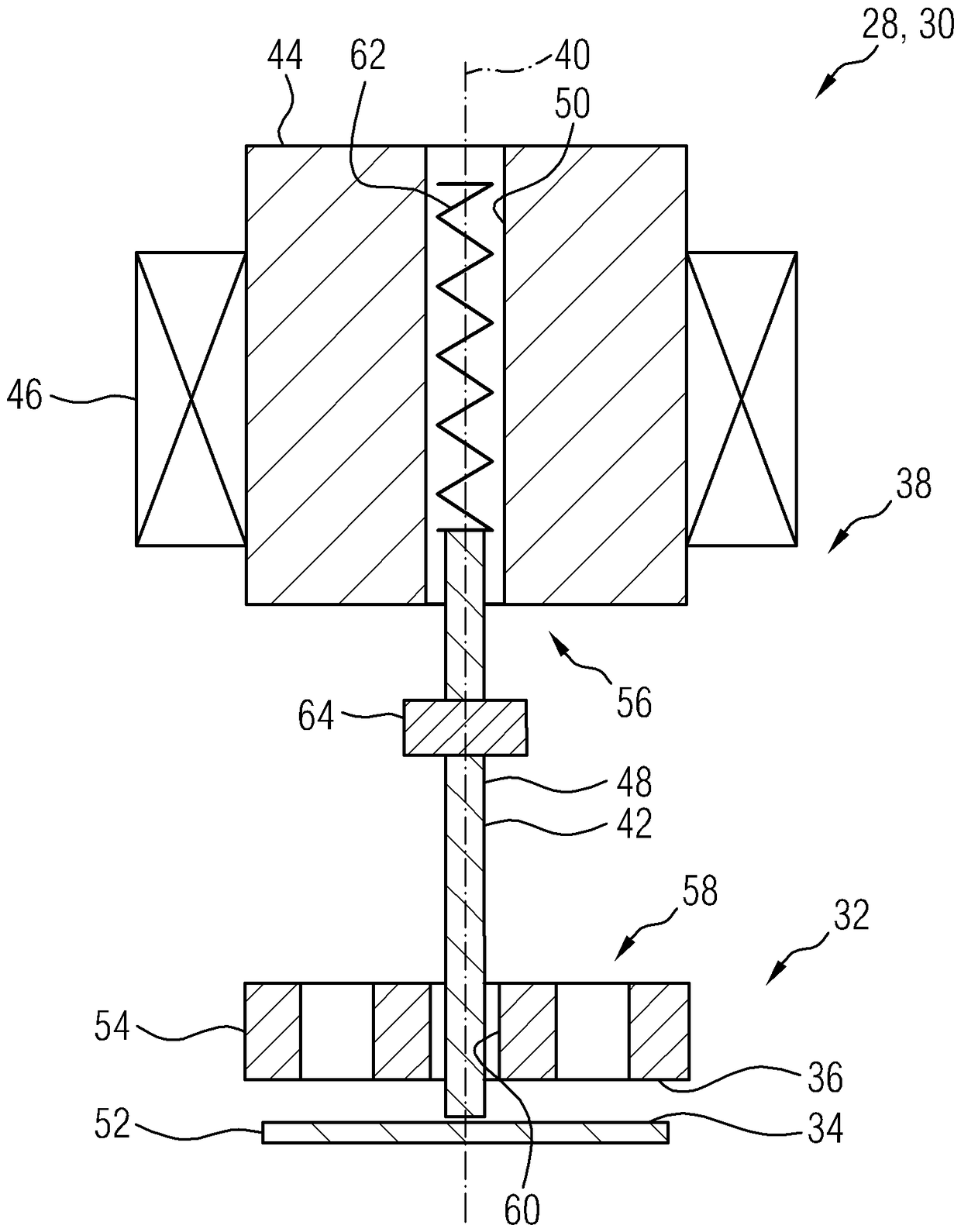
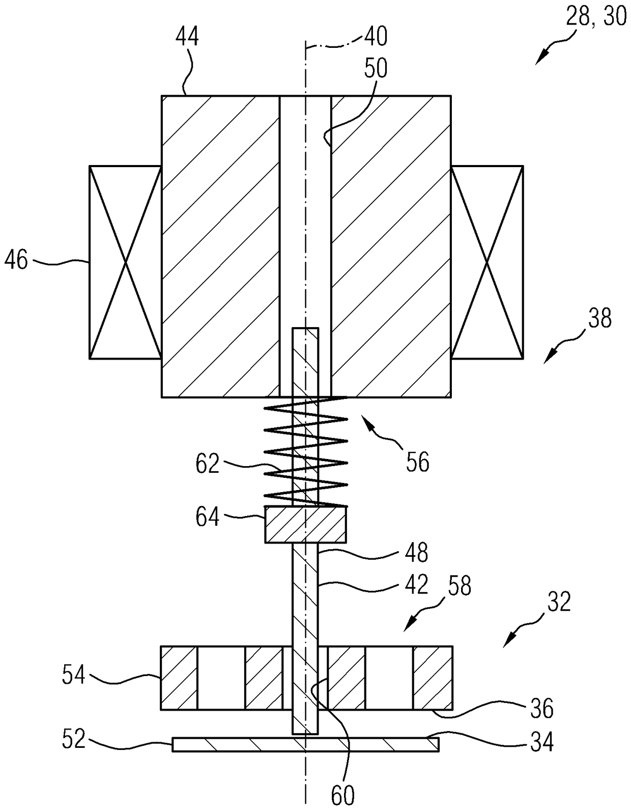
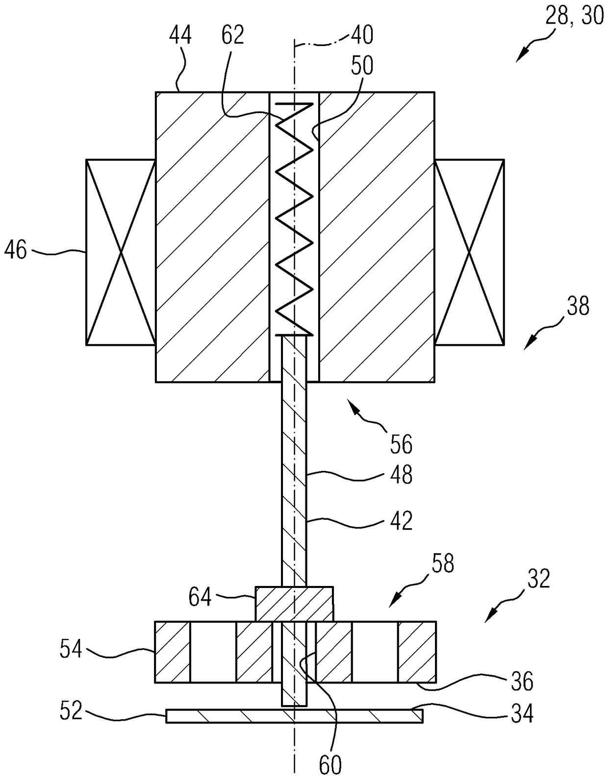
[0040] The inlet valve 24 is designed as a solenoid valve 28 , in particular as a volume flow control valve 30 , and can thus actively regulate the delivery of fuel 12 in the high-pressure fuel pump 18 by targeted changes in the closing or opening times. Spend.

[0041] exist Figure 2 to Figure 7 In , the solenoid valve 28 is shown in more detail in schematic cross-sectional views in different embod...


PUM


Abstract

There is disclosed a solenoid valve (28) for a fuel injection system (10), in which a closing element (34) which interacts with a valve seat (36) in order to close and open the solenoid valve (28) isactuated by a control pin (42), wherein the control pin is formed by way of a solenoid plunger (48). Furthermore, a high pressure fuel pump (18) is disclosed which has a solenoid valve (28) of this type.

Description

technical field [0001] The invention relates to a solenoid valve for a fuel injection system of an internal combustion engine and to a high-pressure fuel pump having such a solenoid valve. Background technique [0002] In fuel injection systems in internal combustion engines, the fuel is usually subjected to a high pressure, wherein the pressure lies, for example, in the range of 150 bar to 400 bar in gasoline internal combustion engines and in the range of 1500 bar to 2500 bar in diesel internal combustion engines Inside. The greater the pressure that can be generated in the respective fuel, the lower the emissions produced during the combustion of the fuel in the combustion chamber, which is advantageous in particular against the background of the growing desire to reduce emissions. [0003] In a fuel injection system valve arrangements can be provided at various points on the path that the fuel takes from the fuel tank to the corresponding combustion chamber of the inter...

Claims


Application Information

Patent Timeline
IPC IPC(8): F02M59/46
CPCF02M59/466F02M59/368F02M63/0021F02M63/0033F02M63/0071F02M63/0075F02M63/0077F02M63/0078F02M2200/02F02M2200/09F02M37/0023F02M63/0015F02D41/406F02D2200/0602F02D2250/31F02M47/027F02M59/365F02M59/464F02M63/0019F02M2200/40
Inventor T.富克斯
Owner CONTINENTAL AUTOMOTIVE GMBH
Why Eureka
Try Eureka