Electric automatic guided vehicle braking device and braking method

A technology of automatic guided vehicles and braking devices, applied in the direction of braking transmission devices, brakes, vehicle components, etc., can solve the problems of complex structure and inaccurate braking force output, and achieve accurate calculation, precise control of braking force, and operation easy effect

Active Publication Date: 2019-08-23
ZHEJIANG LEAPMOTOR TECH CO LTD
View PDF4 Cites 0 Cited by
  • Summary
  • Abstract
  • Description
  • Claims
  • Application Information

AI Technical Summary

Problems solved by technology

[0003] The purpose of the present invention is to overcome the shortcomings of inaccurate braking force output and complex structure in the prior art, and provide an electric automatic guided vehicle braking device and braking method that can accurately control the braking force output and is easy to operate

Method used


Image

  • Electric automatic guided vehicle braking device and braking method
  • Electric automatic guided vehicle braking device and braking method

Examples


Embodiment Construction

[0035] The present invention will be further described below in conjunction with the accompanying drawings and specific embodiments.

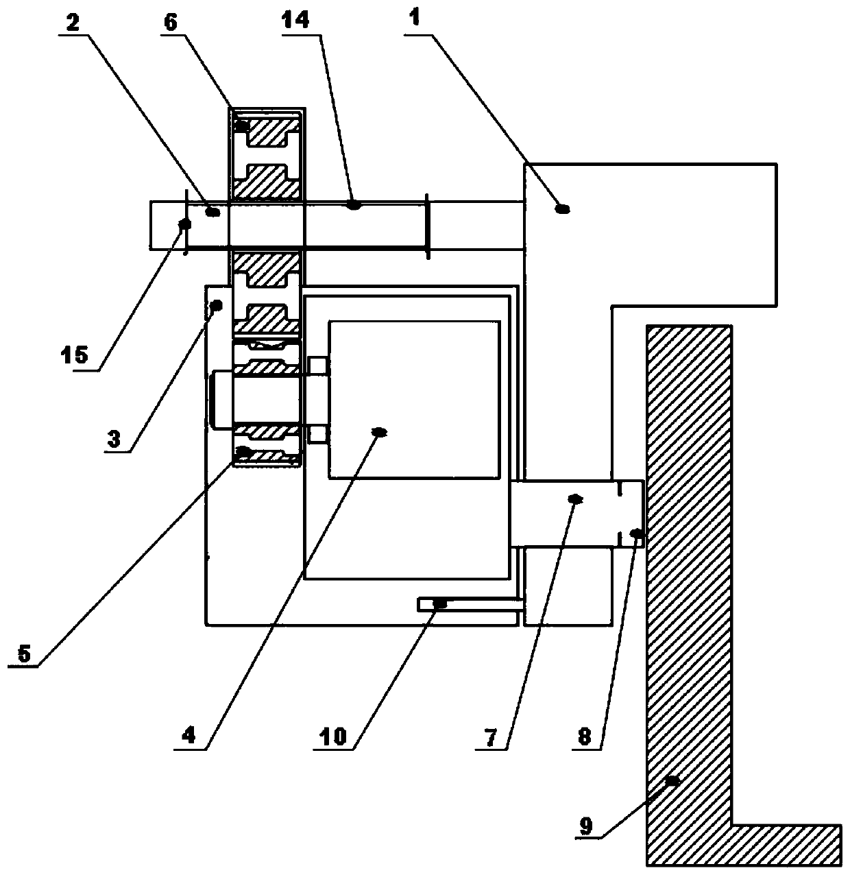
[0036] Such as figure 1 The illustrated embodiment is a braking device for an electric automatic guided vehicle, comprising a vehicle frame 1, a horizontal screw 2 connected to the vehicle frame, a housing 3 located at the bottom of the screw, a motor 4 located in the housing, and a motor 4 located in the housing. The first gear 5 on the rotating shaft of the motor, the second gear 6 on the upper part of the first gear meshed with the first gear, the second gear is connected with the horizontal screw in rotation, the push rod 7 arranged on the outside of the bottom of the housing, the push rod One end is connected with the lower part of the housing, and the other end of the push rod is connected with the friction block 8, which is arranged on the tire transmission disc 9 at the bottom of the vehicle frame, and the friction block can be in conta...


PUM


Abstract

The invention discloses an electric automatic guidance vehicle braking device. The device comprises a frame, a horizontal screw connected with the frame, a shell arranged at the lower part of the screw, a motor arranged in the shell, a first gear arranged on a rotary shaft of the motor, a second gear which is arranged at the upper part of the first gear, meshed with the first gear and rotationallyconnected with the horizontal screw, a push rod on the outer side of the bottom of the shell, a tire transmission disc arranged on the lower part of the frame, a position sensor on the frame, a vehicle-mounted controller on a guidance vehicle, a gyroscope arranged on the guidance vehicle, and a console arranged in a control center, wherein one end of the push rod is connected with the lower portion of the shell, the other end of the push rod is connected with a friction block, the friction block can be in contact with the tire transmission disc, the motor is fixed to the inner surface of theshell, the console is electrically connected with the vehicle-mounted controller, and the vehicle-mounted controller is electrically connected with the position sensor, the motor and the gyroscope. The device has the advantages of being capable of precisely controlling braking force output and convenient to operate.

Description

technical field [0001] The invention relates to the technical field of automatic guided vehicle braking, in particular to an electric automatic guided vehicle braking device and braking method that can precisely control the output of braking force and is easy to operate. Background technique [0002] The traditional brake system adopts the mode of brake pedal, booster master cylinder, brake oil pipe, and wheel brake. The driver manipulates the brake pedal, and after the booster boosts, the oil pressure is established in the brake master cylinder, and the braking force is controlled. The dynamic oil pipe transmits the oil pressure to the wheel brake to realize braking. Due to the large number of transmission structures, the output braking force cannot be precisely controlled, and active braking cannot be performed. Compared with traditional cars, automatic guided vehicles have more precise and controllable requirements for braking force, and can actively brake. Contents of...

Claims


Application Information

Patent Timeline
Patent Type & Authority Patents(China)
IPC IPC(8): B60T13/74B60T8/171B60T8/32
Inventor 宋建勋
Owner ZHEJIANG LEAPMOTOR TECH CO LTD
Why Eureka
Try Eureka