
Image sensor and forming method thereof

An image sensor and pixel area technology, applied in the field of image sensors, can solve problems such as color sensitivity reduction, image sensor phase detection ability degradation, signal interference, etc., and achieve the effect of increasing process cost, good light blocking effect, and easy process realization

Inactive Publication Date: 2018-07-13
HUAIAN IMAGING DEVICE MFGR CORP
View PDF3 Cites 7 Cited by
  • Summary
  • Abstract
  • Description
  • Claims
  • Application Information

AI Technical Summary

Problems solved by technology

[0005] The technical problem solved by the present invention is the degradation of the phase detection ability of the image sensor in the prior art, the existence of signal interference, and the reduction of color sensitivity.

Method used


Image

  • Image sensor and forming method thereof
  • Image sensor and forming method thereof
  • Image sensor and forming method thereof

Examples


Embodiment Construction

[0044] An embodiment of the present invention provides an image sensor, and the embodiments of the present invention will be described in detail below with reference to the accompanying drawings.

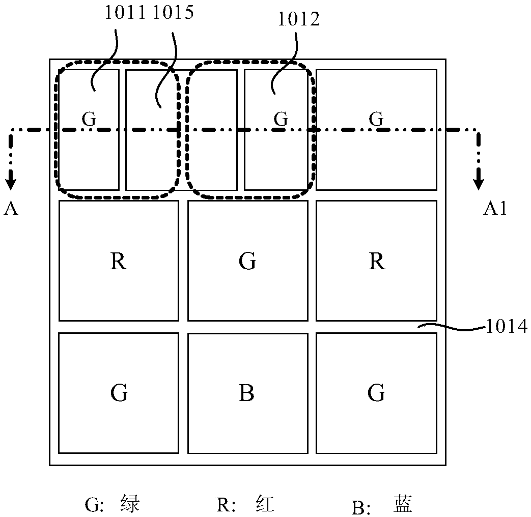
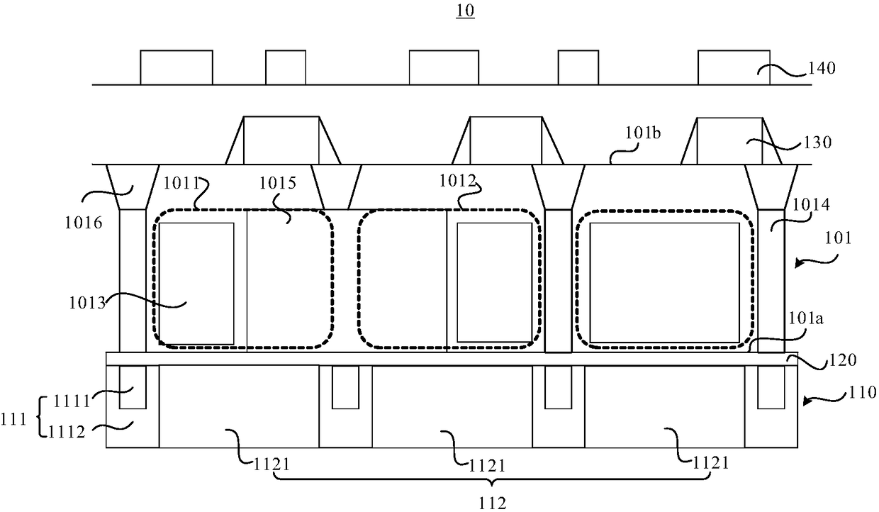
[0045] refer to Figure 1 to Figure 2 , figure 1 is a top view of a pixel area of ​​an image sensor 10 according to an embodiment of the present invention, figure 2 yes figure 1 The schematic diagram of the cross-sectional structure of the image sensor 10 along the line AA1 is shown.

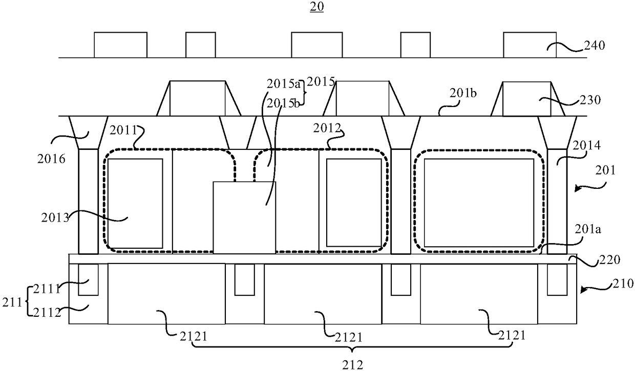
[0046] In some embodiments, the image sensor 10 includes: a substrate 101 in which a plurality of pixel regions (such as figure 2 shown in the dotted line box), and the first Deep Trench Isolation (Deep Trench Isolation, DTI) 1014 between adjacent pixel regions, each pixel region is provided with a photoelectric conversion element 1013; and the filter layer 110 is set On the first surface 101a of the substrate 101, the filter layer 110 includes: a grid 111, the grid 111 has a plurality of openin...


PUM


Abstract

The invention provides an image sensor and a forming method thereof. The image sensor comprises a substrate and a light filter layer; the substrate comprises multiple pixel zones and first deep trenchisolations located between the adjacent pixel zones; each pixel zone is provided with a photovoltaic conversion element; the light filter layer is arranged at the first surface of the substrate and comprises a grid and color filter elements; the grid is provided with multiple openings, and each opening corresponds to one pixel zone in the substrate, and the color filter elements are arranged in the openings; the multiple pixel zones comprise a first pixel zone and a second pixel zone which are used as phase detecting pixels; the first pixel zones and the second pixel zones are provided with second deep trench isolations; the second deep trench isolations and the photovoltaic conversion element at the first surface are provided with light receiving faces, and thus part of light emitted tothe first pixel zones and the second pixel zones is emitted to the light receiving face of the photovoltaic conversion element and the other part is emitted to the light receiving face of the second deep trench isolations.

Description

technical field [0001] The present invention relates to the technical field of image sensors, in particular to an image sensor with phase detection pixels and a forming method thereof. Background technique [0002] Some pixels in the photosensitive area are sacrificed, and these pixels are called masked pixels (Masked Pixels). The masked pixel is usually composed of two pixels, where the left pixel is used to capture the left image, and the right pixel is used to capture the right image. By comparing the values ​​of the left image and the right image with the reference signal, it can be judged that the lens should move forward Or move back to achieve focus. [0003] Masking pixels are applied to CMOS image sensors to improve the focus of the camera through phase detection, also known as "phase detection pixels (Phase Detection Pixel, PDP)". In the prior art, a back-illuminated (BSI) CMOS image sensor with a PDP sets a PDP mask in a composite grid to realize a phase detecti...

Claims


Application Information

Patent Timeline
Patent Type & Authority Applications(China)
IPC IPC(8): H01L27/146
CPCH01L27/14605H01L27/14609H01L27/1463H01L27/14687
Inventor 丁琦黄晓橹陈世杰内藤逹也
Owner HUAIAN IMAGING DEVICE MFGR CORP
Learn More