
Geological exploration sampler

A technology of geological exploration and sampler, which is applied in the direction of sampling device, etc., can solve the problem of inconvenient sampling of soil sampler, and achieve the effect of avoiding pinching and ensuring stability.

Inactive Publication Date: 2018-07-13
EAST CHINA UNIV OF TECH
View PDF7 Cites 1 Cited by
  • Summary
  • Abstract
  • Description
  • Claims
  • Application Information

AI Technical Summary

Problems solved by technology

[0004] The purpose of the present invention is to overcome the deficiencies of the prior art, adapt to the actual needs, and provide a geological exploration sampler to solve the problem of inconvenient sampling of the existing soil sampler

Method used


Image

  • Geological exploration sampler
  • Geological exploration sampler
  • Geological exploration sampler

Examples


Embodiment 1

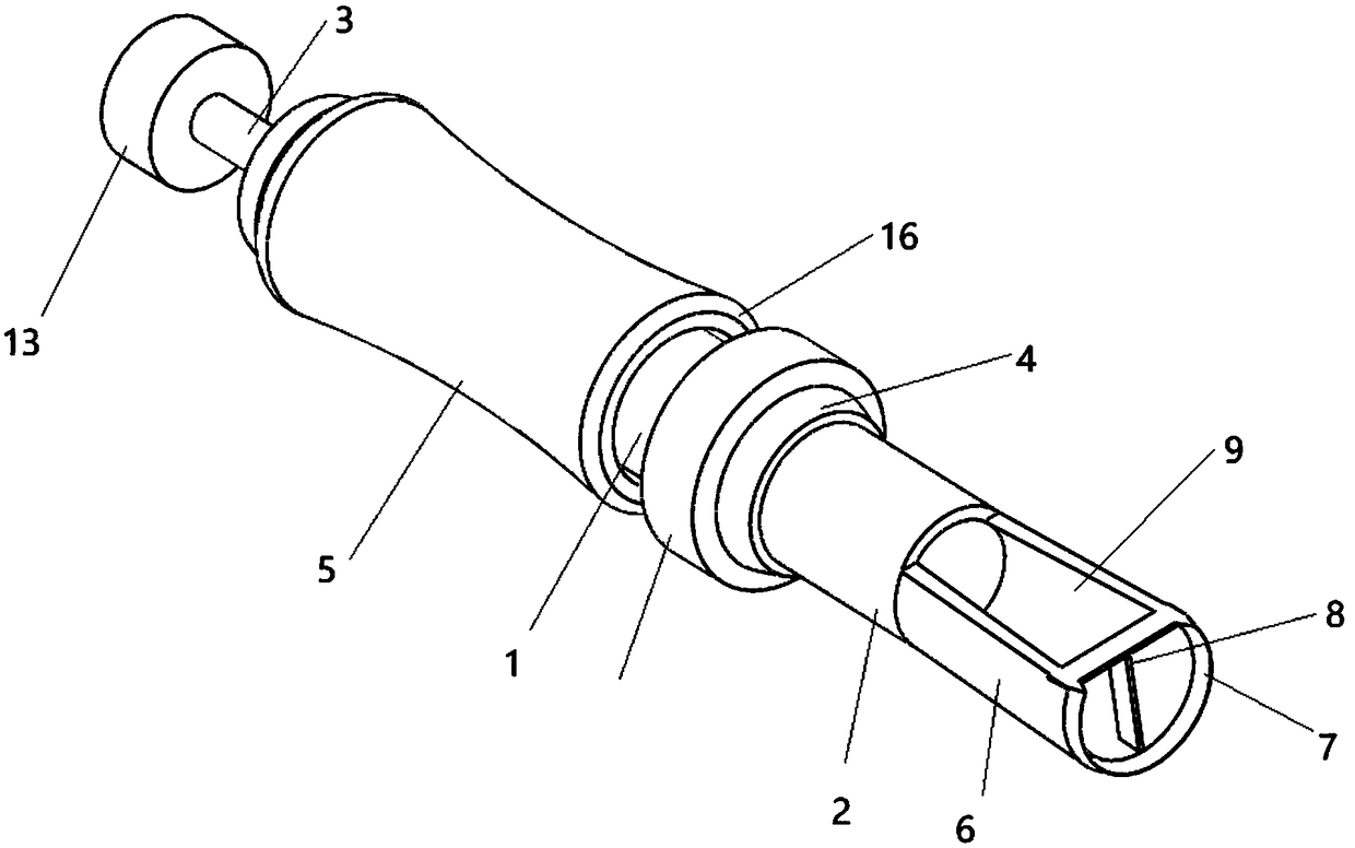
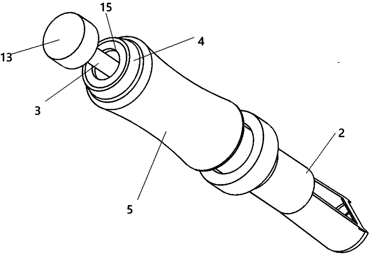
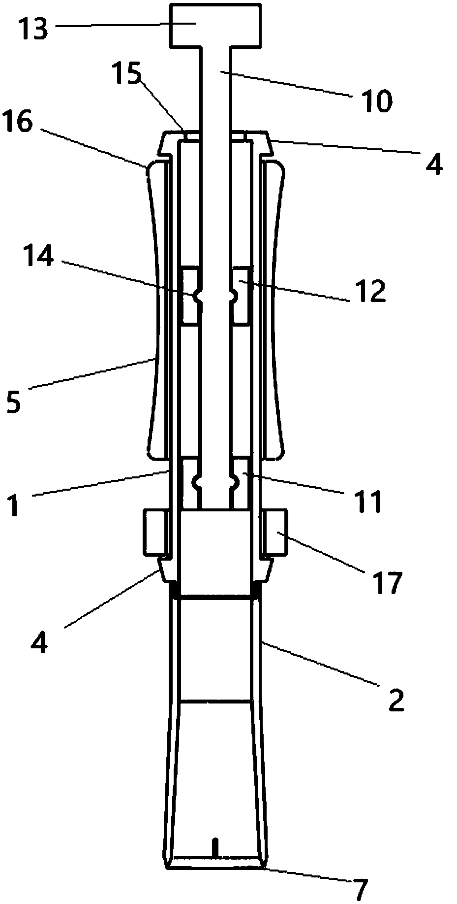
[0023] like Figures 1 to 3 , a sampler for geological exploration, comprising a cylinder 1, a head 2 connected to one end thereof, and a push-pull rod 3 arranged in the cylinder 1, and both ends of the cylinder 1 are provided with protruding impact flanges 4 , the cylinder body 1 is surrounded by an impact handle 5, the impact handle 5 is a hollow body with thick ends and a thin middle, and there is a back and forth sliding between the impact convex edges 4, and the end 2 is provided with a drill bit 6. The peripheral cutting knife 7 and the loosening knife 8 that the drill bit 6 includes, the cutting knife 7 is circular and has an opening 9 on one side, and the loosening knife 8 consists of two blades that are T-shaped and vertical Connect and be arranged on the 7 ends of cutting knife, described push-pull rod 3 comprises rod body 10, first piston 11 and second piston 12, described rod body 10 afterbody is provided with push-pull handle 13, and described rod body 10 head and...

Embodiment 2

[0027] The difference between this embodiment and Embodiment 1 is that for some sandy soil sampling, the structure of the tip can be designed in the shape of a spiral blade, which is convenient for rotating sampling, so the structure of the tip can be changed according to different types of sampling soil. Structure.

[0028] Compared with the existing soil sampling structure, the present invention adopts a drill bit structure in which a cutting knife cooperates with a loose soil knife, and uses a circular cutting knife to separate the sampled soil, and then uses a loose soil knife to separate the hard soil after cutting. Crushing, T-shaped soil loosening knife can have better crushing effect; the addition of impact convex edge and impact grip can realize the use of impact inertia to make the drill bit inserted deeper, which is convenient for sampling deep soil, and the design with side opening can facilitate the sampling after sampling. Topple over; in order to ensure that the...


PUM


Abstract

The invention relates to a geological exploration tool, in particular to a geological exploration sampler in order to solve the problem of inconvenience in sampling of an existing soil sampler. The geological exploration sampler comprises a barrel body, an end socket connected with one end of the barrel body, and a push-pull rod arranged in the barrel body. Protruding impact flanges are arranged at both ends of the outer side of the barrel body; an impact handle is arranged around the barrel body; the impact handle is a hollow body with two thick ends and a thin middle part, and slides back and forth between the impact flanges; a drill bit is arranged on the end socket; the drill bit comprises a peripheral cutting tool and a soil loosening tool; the cutting tool is of a circular table ringshape, and an opening is formed in one side of the cutting tool; and the T-shaped soil loosening tool is vertically connected to the end part of the cutting tool through two blades. Compared with anexisting soil sampling structure, the geological exploration sam\\\pler disclosed by the invention adopts a drill bit structure where the cutting tool is matched with the soil loosening tool; the annular cutting tool is used for separating sampled soil, and then the soil loosening tool is used for smashing cut hard soil; and the T-shaped soil loosening tool is relatively good in smashing effect.

Description

technical field [0001] The invention relates to a geological exploration tool, in particular to a geological exploration sampler. Background technique [0002] "Geology", also called geology, mainly studies the earth and its origin and evolution. Practical applications include: prediction of earthquakes, search and exploration of various minerals, disastrous landslides, and evolution of paleontology. Geological prospecting is the discovery of mineral deposits with industrial significance in the general survey of mineral resources. In order to ascertain the quality and quantity of mineral products, as well as the technical conditions for mining and utilization, provide mineral reserves and geological data required for mine construction design, and analyze rocks in a certain area. , formation, structure, minerals, hydrology, geomorphology and other geological conditions to conduct investigation and research work. [0003] Exploration samplers in the prior art are usually com...

Claims


Application Information

Patent Timeline
Patent Type & Authority Applications(China)
IPC IPC(8): G01N1/08
CPCG01N1/08
Inventor 黄美化刘帅
Owner EAST CHINA UNIV OF TECH
Learn More