
Positioning and checking tool for side vertical control over optical prisms and processing method

A positioning tooling and side positioning technology, which is applied in the direction of manufacturing tools, optical surface grinders, metal processing equipment, etc., can solve the problem that the positioning accuracy of side sagging is difficult to achieve, and achieve simple and fast positioning, avoid loosening or falling, and increase bonding intensity effect

Pending Publication Date: 2018-07-13
马鞍山市江南光学有限公司
View PDF1 Cites 6 Cited by
  • Summary
  • Abstract
  • Description
  • Claims
  • Application Information

AI Technical Summary

Problems solved by technology

[0007] The invention provides a positioning tool for optical prism side sag control, and its purpose is to solve the problem that the side sag positioning accuracy is difficult to reach within 20" in the existing prism processing

Method used


Image

  • Positioning and checking tool for side vertical control over optical prisms and processing method
  • Positioning and checking tool for side vertical control over optical prisms and processing method
  • Positioning and checking tool for side vertical control over optical prisms and processing method

Examples


Embodiment 1

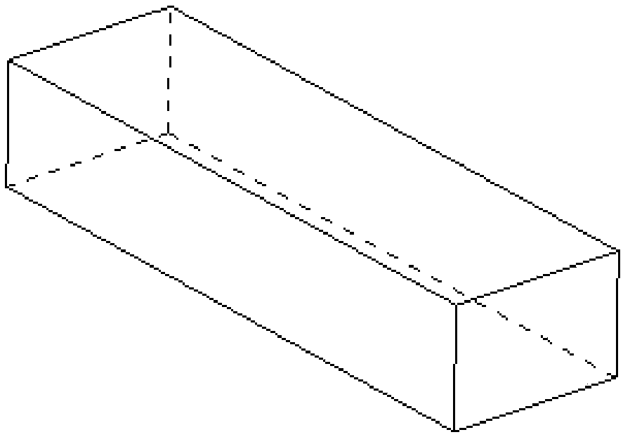
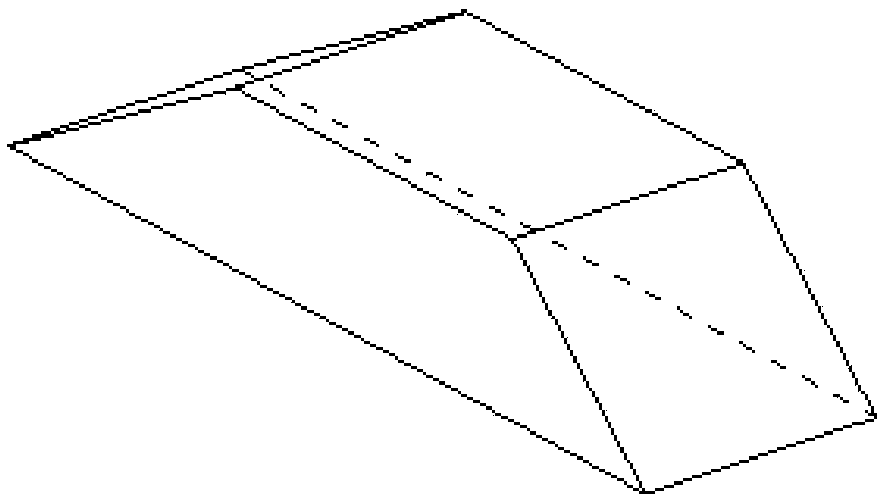
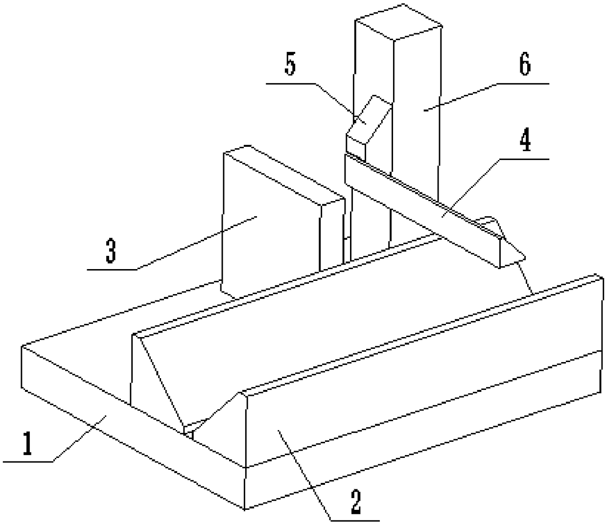
[0048] Such as image 3 As shown, a positioning tool for optical prism side sag control in this embodiment is specially designed for grinding the bevels at both ends of a square prism. figure 1 The semi-finished square prism shown is ground into figure 2 Finished product shown. The square prism requires that the angle between the inclined surfaces at both ends and the upper and lower bottom surfaces is 45°, and the perpendicularity accuracy with the front and rear sides, that is, the side sag accuracy is within 20". The positioning tool structure will be described below.

[0049] The positioning tool of this embodiment includes a base plate 1 , a positioning prism 2 , an end face positioning block 3 , a side positioning block 4 , a connecting block 5 and a supporting block 6 . Wherein, the positioning prism 2, the end face positioning block 3 and the supporting block 6 are placed on the substrate 1; the positioning prism 2 and the side positioning block 4 are all isosceles ...

Embodiment 2

[0054] Such as Figure 4 As shown, a calibration tool for side sag control of an optical prism in this embodiment is specially designed for the positioning and installation of the positioning tool for side sag control of an optical prism in Embodiment 1. It mainly comprises a reference triangular prism 7 and a reference square prism 8; wherein, the reference triangular prism 7 is an isosceles right-angled prism, the reference square prism 8 is fixed on the slope of the reference triangular prism 7, and the reference square prism 8 is a regular hexagon. Reference triangular prism 7 cooperates with the V-shaped positioning groove that two positioning triangular prisms 2 form, wherein two adjacent sides of reference square prism 8 are used as detection surfaces, cooperate with the end positioning surface of end face positioning block 3 and the side positioning block 4 respectively. Side locating face fit.

[0055] The reference triangular prism 7 and the reference square prism 8...

Embodiment 3

[0059] A kind of processing method of side sagging control of optical prism in this embodiment is used to figure 1 The semi-finished square prism shown is processed into figure 2 For the finished square prism shown, the bevels at both ends are ground and processed to ensure that the side sag accuracy of the bevel and the front and rear sides of the square prism is within 20″.

[0060] The operation steps of the processing method of optical prism side sag control are as follows:

[0061] 1. Assembly of positioning tooling

[0062] Adopt the positioning tooling of the optical prism side droop control of the optical prism side droop control of the optical prism side droop control in the assembly embodiment 1 of embodiment 2; Figure 5 As shown, the specific assembly steps are:

[0063] ①Take a positioning prism 2 and press it on the upper surface of the substrate 1 to generate interference fringes, and glue it together with optical glue; put the V-shaped bottom side of the re...


PUM


Abstract

The invention discloses a positioning and checking tool for side vertical control over optical prisms and a processing method, and belongs to the technical field of optical prism processing. The positioning tool comprises a base plate, positioning triangular prisms, an end surface positioning block and a side surface positioning block; the two positioning triangular prisms are oppositely arrangedon the base plate and form a V-shaped positioning groove; the end surface positioning block is arranged on the position, on one sides of the positioning triangular prisms, of the base plate and is provided with an end positioning surface; the end positioning surface is perpendicular to the upper surface of the base plate and is perpendicular to the projection plane, on the base plate, of the groove surface of the V-shaped positioning groove; the side positioning block is arranged above the V-shaped positioning groove and is provided with a side positioning surface; and the side positioning surface is perpendicular to the groove surface of the v-shaped positioning groove and the end positioning surface of the end surface positioning block. The processing method comprises the following stepsof firstly, assembling the positioning tool through a checking tool; then carrying out vertical positioning on a square prism by using the positioning tool; and finally, grinding the bevels at the two ends of the square prism. According to the positioning and checking tool and the processing method, the square prism can be conveniently and quickly positioned, and the side vertical precision of the bevels at the two ends can be guaranteed to be within 20 arc seconds.

Description

technical field [0001] The invention belongs to the technical field of optical prism processing, and more specifically relates to a positioning and checking tool and a processing method for side droop control of an optical prism. Background technique [0002] A prism is a prism composed of optical materials. The refracting and reflecting surfaces of all prisms are collectively called the working surface, the intersection line of the two working surfaces is called the prism, and the section perpendicular to the prism is called the main section. Prisms play many different roles in optics. The combination of prisms can be used as beam splitters, polarizers, etc., but in most applications, only the dispersion function of prisms is used, or the direction of the image, the beam A function that changes the direction of propagation. The dispersion function makes the prism act as a dispersion element, such as the prism in the spectrometer, spectrograph, and monochromator, it plays t...

Claims


Application Information

Patent Timeline
IPC IPC(8): B24B13/00B24B13/005B24B1/00
CPCB24B1/00B24B13/00B24B13/005Y02P40/57
Inventor 金正彬
Owner 马鞍山市江南光学有限公司
Learn More