
Occluder and suturing method of occluder

An occluder and suture hole technology, applied in the field of medical devices, can solve the problems of enlarged disk surface, reduced surgical safety and effectiveness, and inability to completely block the defect, so as to improve safety and effectiveness, and improve complete blocking. the effect of the possibility of

Active Publication Date: 2020-06-12
LIFETECH SCIENTIFIC (SHENZHEN) CO LTD
View PDF10 Cites 1 Cited by
  • Summary
  • Abstract
  • Description
  • Claims
  • Application Information

AI Technical Summary

Problems solved by technology

[0004] However, when the sealing disk is retracted into the sheath, due to the pushing action of the edge of the sheath mouth on the suture during this process, the sealing disk mesh The intersection with the suture moves toward the distal end of the occluder, thereby crimping the membrane
In addition, when there is no external force on the sealing disc, the grid intersection of the sealing disc moves to the distal end of the occluder during the process of entering the sheath and the resilience of the sealing disc made of polymer material is stronger than that of nickel The sealing disk formed by the titanium wire has poor resilience, so the surface of the sealing disk of the occluder becomes larger, which leads to the blockage after the occluder is released (that is, the occluder is in a natural state without external force). The edge of the membrane cannot reach the edge of the sealing disc surface of the occluder, so that there will be residual shunt blood in the defect part of the patient, and the defect part cannot be completely blocked, which reduces the safety and effectiveness of the operation

Method used

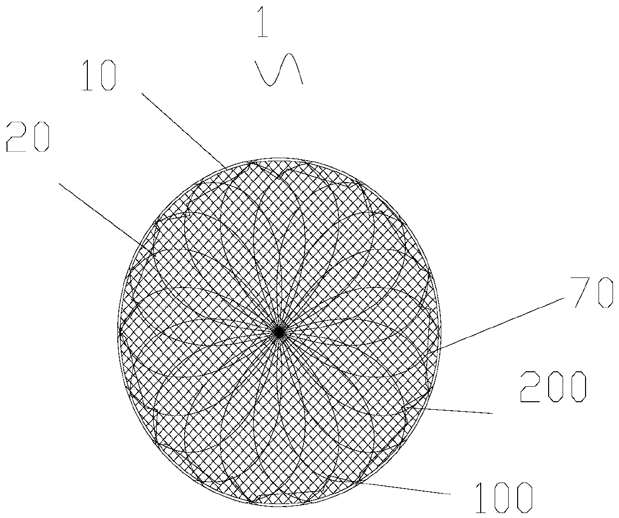
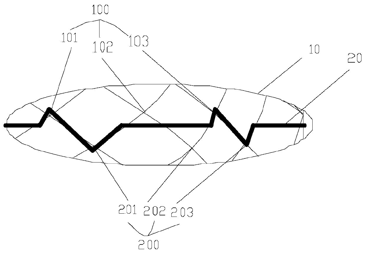
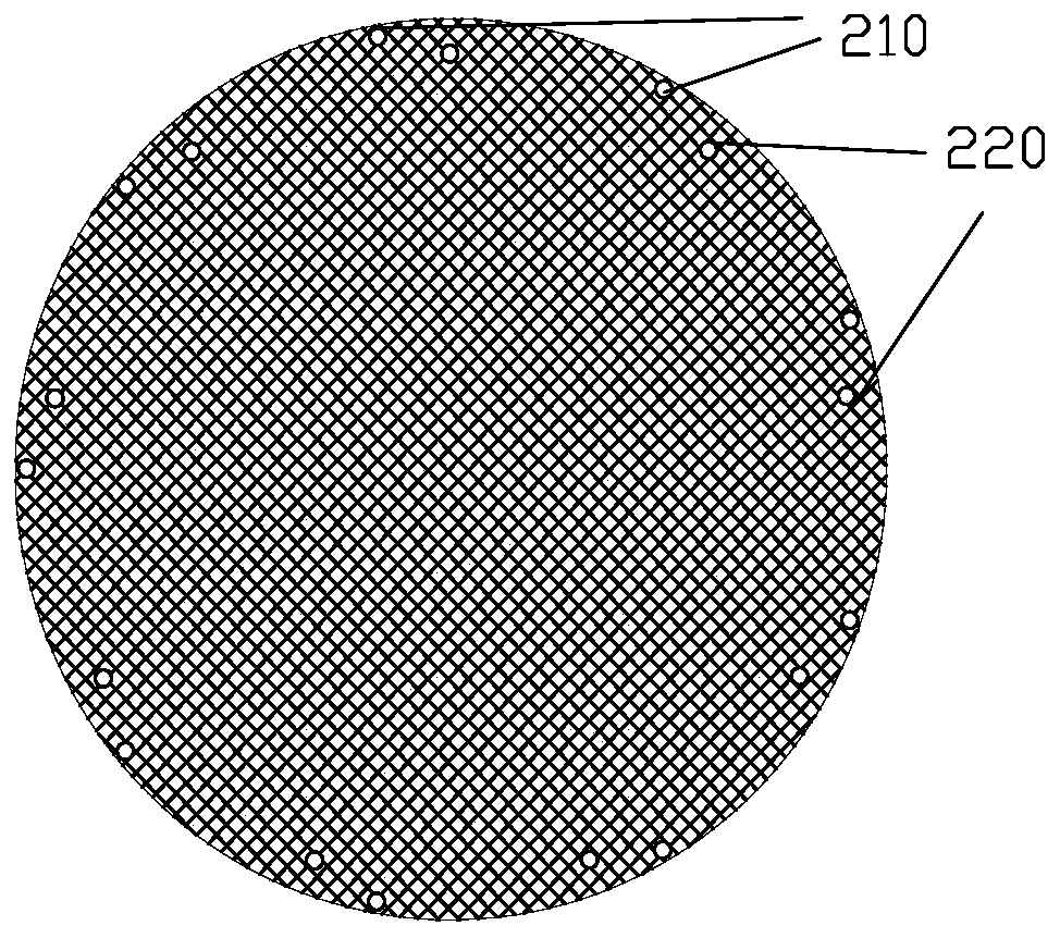

Image

  • Occluder and suturing method of occluder
  • Occluder and suturing method of occluder
  • Occluder and suturing method of occluder

Examples


Embodiment Construction

[0024] In order to make the object, technical solution and advantages of the present invention clearer, the present invention will be further described in detail below in conjunction with the accompanying drawings and embodiments. It should be understood that the specific embodiments described here are only used to explain the present invention, not to limit the present invention.

[0025] Unless otherwise defined, all technical and scientific terms used herein have the same meaning as commonly understood by one of ordinary skill in the technical field of the invention. The terms used herein in the description of the present invention are for the purpose of describing specific embodiments only, and are not intended to limit the present invention. As used herein, the term "and / or" includes any and all combinations of one or more of the associated listed items.

[0026] The inventive spirit of the present invention lies in that the suturing points of the choke membrane and the ...


PUM


Abstract

The invention relates to an occluder, comprising a first disc-shaped structure with grids, the first disc-shaped structure is braided by at least two sets of braided wires, the two sets of braided wires are crossed to form multiple cross points, and the first disc-shaped structure is A choke film is also arranged in the structure, and the edge of the choke film is connected with the intersection of the outermost circle of the intersections of the multiple circles by a suture, and the number of intersections sutured with the choke film in the intersection of the outermost circle is less than the number of the intersection points of the outermost circle. The number of all intersections in the intersection of the outer circle, and the position of the blocking membrane close to its edge is connected with a circle of intersections in the intersection of the outermost circle among the intersections of multiple circles by sutures. The invention can reduce the possibility of occurrence of the phenomenon that the edge of the blocking film cannot reach the edge of the disk surface of the occluder, thereby improving the blocking effect of the occluder.

Description

technical field [0001] The invention relates to the technical field of medical devices, in particular to an occluder and a suturing method for the occluder. Background technique [0002] A heart defect occluder is an implantable medical device for treating congenital heart defects, and its usual structure mainly includes a sealing disc, a flow-blocking membrane, and sutures. The blocking membrane plays the role of sealing the defect and blocking the blood shunt. The barrier membrane is secured to the edge of the largest diameter of the sealing disc by means of sutures. [0003] Most of the clinically used occluders currently on the market are braided by nickel-titanium alloy wires. Due to the long-term existence of nickel-titanium alloy wire in the human body, it is easy to cause the rejection of the biological body, and the existence of nickel ions is easy to cause allergies and corresponding complications, and even a certain degree of damage, which will affect the heart ...

Claims


Application Information

Patent Timeline
Patent Type & Authority Patents(China)
IPC IPC(8): A61B17/00
CPCA61B17/0057A61B2017/00597A61B2017/00575A61B2017/00606A61B2017/00623A61B17/00A61B2017/00592A61B2017/00243A61B2017/00601A61B2017/00654A61B17/06166A61B2017/00526A61B2017/00663A61B2017/00867A61L17/12
Inventor 张杰陈贤淼邓月英李文锋
Owner LIFETECH SCIENTIFIC (SHENZHEN) CO LTD
Learn More