Network congestion determination method and device

A technology of network congestion and determination method, applied in the field of communication, which can solve the problems of private protocol, retransmission, slow business transaction, etc.

Active Publication Date: 2018-07-06
CHINA MOBILE GROUP ZHEJIANG +1
View PDF7 Cites 8 Cited by
  • Summary
  • Abstract
  • Description
  • Claims
  • Application Information

AI Technical Summary

Problems solved by technology

[0002] With the widespread introduction of cloud computing and big data in the industry, these new technologies put forward higher requirements for network bandwidth and delay. Since the DCN network is usually based on the TCP / IP protocol, the protocol itself has inherently insufficient flow control capabilities, and it is easy to Node congestion occurs, manifested as delay, TCP retransmission, timeout or even discarding, and at the business level, it manifests as slow business transactions, and generally has the characteristics of persistence and business perception lag
Considering that in the process of DCN network development in most companies, the introduction of multiple manufacturers has problems such as various hardware brands, different support features, and private protocols, it is difficult to conduct global analysis through data flow sampling technologies such as Sflow and Netflow
[0003] At present, when network engineers detect and deal with congestion, they usually combine alarms and manual investigations, and complete the process through the following processes: receive alarms such as port bandwidth exceeding the threshold, log in to the device to confirm information (logs, routing tables, port status, etc.); Investigate a large number of port traffic monitoring chart information, check the ip flow information of the core equipment, and the positioning success rate is low; through manual investigation, communicate whether there is a large traffic timing task in the source-destination center of the congested link; detect the network at the site where the congested link device is located Data packets, locate the source and destination IP to limit
[0004] In the process of realizing the embodiment of the present invention, the inventors found that the existing method involves many network nodes and lines due to the global nature of network links, and it is difficult to judge congestion. And indirect means such as locating the source and destination IP to judge network congestion. Congestion judgment lacks objective standards and relies heavily on the experience and ability of network engineers. At the same time, the process of congestion judgment involves alarm information analysis, manual troubleshooting and a lot of communication work, so there are The entire processing process is too long and depends on the experience and ability of engineers. The analysis and judgment time is too long, resulting in too long processing time for the entire congestion, and even the situation where the problem has not been located even after the obvious business impact

Method used


Image

  • Network congestion determination method and device
  • Network congestion determination method and device
  • Network congestion determination method and device

Examples


Embodiment Construction

[0048] The specific embodiments of the present invention will be further described below in conjunction with the accompanying drawings. The following examples are only used to illustrate the technical solution of the present invention more clearly, but not to limit the protection scope of the present invention.

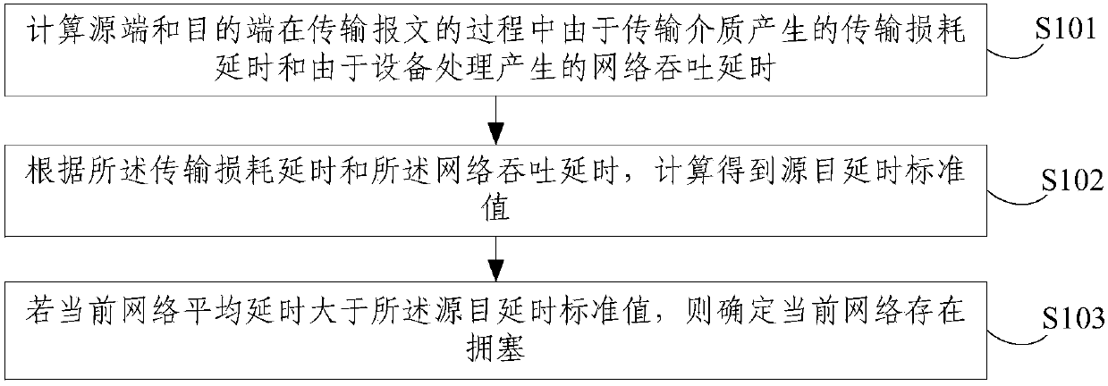
[0049] figure 1 A schematic flowchart of a method for determining network congestion provided by this embodiment is shown, including:

[0050] S101. Calculate the transmission loss delay caused by the transmission medium and the network throughput delay caused by equipment processing during the process of transmitting the message between the source end and the destination end;

[0051] Wherein, the transmission loss delay refers to the transmission delay mainly caused by the transmission medium (including the transmission node device) during the process of transmitting the message between the source end and the destination end.

[0052] For example, when transmittin...


PUM


Abstract

The embodiment of the invention discloses a network congestion determination method and device. The method comprises the following steps: calculating the transmission loss delay caused by a transmission medium and the network throughput delay caused by equipment processing during the transmission of messages by a source end and a destination end; calculating a source-destination delay standard value according to the transmission loss delay and the network throughput delay; and if the current network average delay is greater than the source-destination delay standard value, determining that thecurrent network is congested. The device comprises a delay calculation module, a delay standard value calculation module and a congestion determination module. According to the network congestion determination method and the device provided by the embodiment of the invention, the source-destination delay standard value is further calculated and obtained by calculating the transmission loss delayand the network throughput delay, and the source-destination delay standard value can be used to objectively and quickly determine whether a congestion condition exists between the source end and thedestination end, and there is no need to rely on the experience and capabilities of network engineers.

Description

technical field [0001] The embodiments of the present invention relate to the field of communication technologies, and in particular to a method and device for determining network congestion. Background technique [0002] With the widespread introduction of cloud computing and big data in the industry, these new technologies put forward higher requirements for network bandwidth and delay. Since the DCN network is usually based on the TCP / IP protocol, the protocol itself has inherently insufficient flow control capabilities, and it is easy to Node congestion occurs, manifested as delays, TCP retransmissions, timeouts, and even discards, while at the business level, it manifests as slow business transactions, and generally has characteristics such as continuity and business perception lag. Considering that in the development process of DCN network of most companies, the introduction of multiple manufacturers has problems such as various hardware brands, different support featu...

Claims


Application Information

Patent Timeline
Patent Type & Authority Applications(China)
IPC IPC(8): H04L12/801
CPCH04L47/11H04L47/12H04L47/127
Inventor 吴天东郭岳戴伟张式勤
Owner CHINA MOBILE GROUP ZHEJIANG
Why Eureka
Try Eureka