Support mechanism of crane

A technology of supporting mechanism and crane, which is applied in the direction of bottom supporting structure, hoisting equipment braking device, load hanging components, etc., which can solve the problems of increased volume and weight of cranes, insufficient flexibility and convenience, and prone to warping of legs, etc. , to achieve reasonable structure, increase convenience and flexibility, improve structural strength and service life

Inactive Publication Date: 2018-07-06
HUNAN BAITE LORRY MOUNTED CRANE CO LTD
View PDF3 Cites 1 Cited by
  • Summary
  • Abstract
  • Description
  • Claims
  • Application Information

AI Technical Summary

Problems solved by technology

At present, the support mechanisms of domestic cranes all use circular foot plates, which have a small supporting area, and are prone to problems such as legs warping and local subsidence of the ground.
The greater the lifting capacity required by the crane, the corresponding foot plate area needs to increase accordingly, so that the overall volume and weight of the crane will also increase accordingly, which will have an impact on the driving and working process
In special working conditions, it is necessary to artificially increase the backing plate, which is very troublesome to operate, and the flexibility and convenience are not high enough.

Method used


Image

  • Support mechanism of crane
  • Support mechanism of crane

Examples


Embodiment Construction

[0029] The technical solutions of the present invention will be described in detail below in conjunction with embodiments. The following examples are only used to illustrate the technical solutions of the present invention more clearly, and therefore are only examples, rather than limiting the protection scope of the present invention.

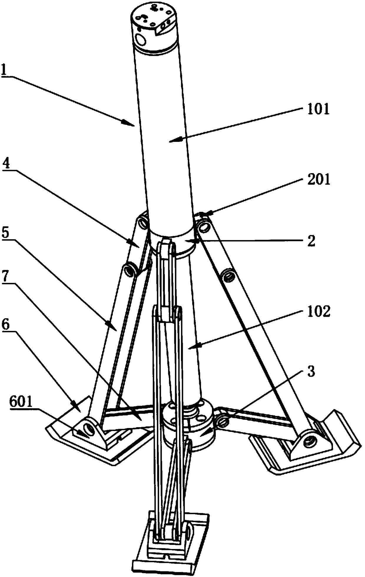
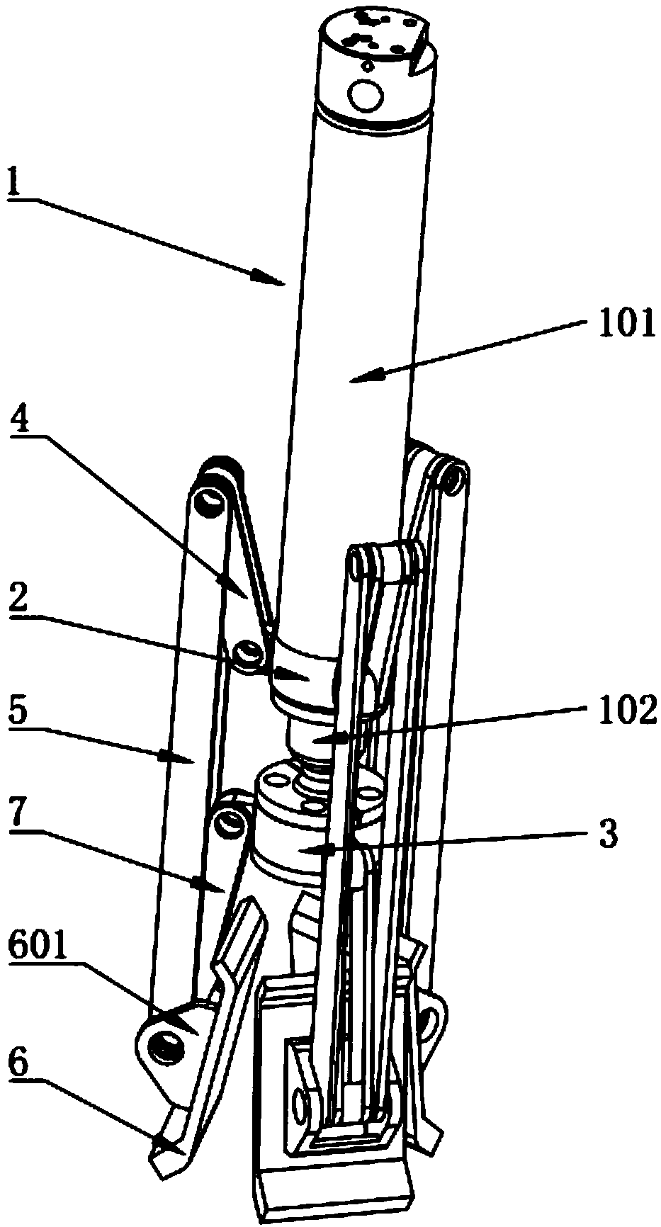
[0030] like Figure 1-2 As shown, a crane support mechanism includes a support cylinder 1, a cylinder barrel 101 of the support cylinder 1 is provided with a rotating sleeve 2, and a piston rod 102 of the support cylinder 1 is connected with a universal support seat 3;

[0031] A number of first connecting rods 4 are hinged on the upper ring of the rotating shaft sleeve 2, and the ends of the first connecting rods 4 are hinged with a second connecting rod 5, and the ends of the second connecting rods 5 are hinged on the side-weight foot plate 6;

[0032] The upper ring of the universal support base 3 is hinged with a third connecting rod 7, t...


PUM


Abstract

The invention belongs to the technical field of cranes, and provides a support mechanism of a crane. The support mechanism comprises a support cylinder, wherein a rotary shaft sleeve sleeves the outerside of a cylinder barrel of the support cylinder, and a universal support seat is connected to a piston rod of the support cylinder; a plurality of first connecting rods are annularly hinged to therotary shaft sleeve, second connecting rods are hinged to the ends of the first connecting rods, and the ends of the second connecting rods are hinged to a bearing support leg plate; and third connecting rods are annularly hinged to the universal support seat, the ends of the third connecting rods are hinged to the bearing support leg plate, and the second connecting rods and the third connectingrods are connected to the same hinged shaft of the bearing support leg plate. According to the support mechanism, the extension and folding of the bearing support leg plate can be controlled by extending and retracting the support cylinder, and the support angle of the bearing support leg plate can be adjusted, so that different working conditions are satisfied, the convenience and flexibility inuse are increased, and the occupied space is reduced; the support mechanism has the advantages of simple structure, stress balance and high stability and is suitable for large-scale popularization anduse.

Description

technical field [0001] The invention relates to the technical field of cranes, in particular to a crane supporting mechanism. Background technique [0002] A crane refers to a multi-action hoisting machine that lifts vertically and carries heavy objects horizontally within a certain range. With the continuous growth of the national economy, continuous infrastructure construction and the outbreak of the logistics market, cranes are used more and more in various fields such as hoisting, maintenance, and emergency rescue. However, there are still some defects in the existing cranes when they are used. At present, the support mechanisms of domestic cranes all use circular foot plates, which have a small supporting area, and are prone to problems such as legs warping and local subsidence of the ground. The greater the lifting capacity required by the crane, the corresponding area of ​​the foot plate needs to increase accordingly, so that the overall volume and weight of the cran...

Claims


Application Information

Patent Timeline
Patent Type & Authority Applications(China)
IPC IPC(8): B66C5/00
CPCB66C5/00
Inventor 周彦明郑昇皇甫少飞
Owner HUNAN BAITE LORRY MOUNTED CRANE CO LTD
Why Eureka
Try Eureka