Rectangular steel bar machining and grinding device

A rectangular, steel bar technology, applied in the direction of grinding drive devices, grinding/polishing safety devices, metal processing equipment, etc., can solve the problems of inability to achieve grinding effects, poor grinding operations, and increased labor costs, etc., to achieve improved Grinding effect, improving sealing effect and improving safety effect

Inactive Publication Date: 2018-07-03
方灼
View PDF0 Cites 0 Cited by
  • Summary
  • Abstract
  • Description
  • Claims
  • Application Information

AI Technical Summary

Problems solved by technology

This kind of device usually can't carry out the grinding operation well, and can't achieve better grinding effect. In order to achieve better grinding effect, the steel strip is generally repeatedly polished. The above-mentioned method is time-consuming and labor-intensive, increases labor costs, and poor vacuuming

Method used


Image

  • Rectangular steel bar machining and grinding device
  • Rectangular steel bar machining and grinding device
  • Rectangular steel bar machining and grinding device

Examples


Embodiment Construction

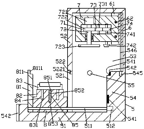
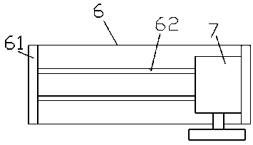
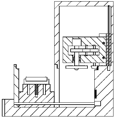
[0024] like Figure 1-Figure 5As shown, a processing and grinding device for a rectangular steel bar of the present invention includes a grinding frame 5 composed of a base 51 and a supporting frame 52. The supporting frame 52 is provided with a grinding cavity 53, and the supporting frame 52 is left A through groove 521 is formed on the side of the side end surface close to the base 51 , a protrusion 54 is fixed on the inner wall of the right side of the grinding cavity 53 opposite to the right side of the through groove 521 , and the top of the left side of the protrusion 54 is fixed. The edge is provided with an opening slot 541 extending front and rear, the right inner wall of the opening slot 541 is fixed with a conical toothed bar 542 extending along the front and rear extension direction of the opening slot 541, and the protruding portion 54 is far away from all the A first threaded rod 546 extending upward is provided on the top end face of one side of the opening groo...


PUM


Abstract

The invention discloses a rectangular steel bar machining and grinding device. The rectangular steel bar machining and grinding device comprises a grinding machine frame composed of a base and a supporting frame. A grinding cavity is formed in the supporting frame. A through groove is formed in the side, close to the base, of the end face of the left side of the supporting frame. A protrusion partis fixedly arranged on the inner wall, opposite to the right side of the through groove, of the right side of the grinding cavity. An opening groove extending front and back is formed in the edge ofthe top of the left side of the protrusion part. A conical toothed strip extending in the front-back extension direction of the opening grove is fixedly arranged on the inner wall of the right side ofthe opening groove. A first threaded rod extending upwards is arranged on the end face of the top of the side, away from the opening groove, of the protrusion part. A lifting bracket of which the endface of the right side abuts against and is connected with the inner wall of the right side of the grinding cavity in a sliding fit mode is connected with the first threaded rod in a threaded fit mode. First baffles are symmetrically arranged on the front side and the rear side of the lifting bracket. Guiding rods are symmetrically arranged between the first baffle on the front side and the firstbaffle on the rear side up and down. A grinding actuating mechanism extending leftwards is connected with the two sets of guiding rods in a sliding fit mode. The rectangular steel bar machining and grinding device is simple in structure, the grinding efficiency and quality are improved, and the grinding safety is high.

Description

technical field [0001] The invention relates to the technical field of industrial production and processing equipment, in particular to a processing and grinding device for rectangular steel bars. Background technique [0002] Steel bars are characterized by light weight, high pressure resistance, good toughness, fast construction, and long life. They are widely used in municipal drainage and sewage, agricultural irrigation, coal mine ventilation, chemical industry, and communication cable sheathing. The surface is rusted, and the rusted steel strip cannot meet the production process requirements. Therefore, it is necessary to polish the surface of the steel strip to remove surface rust. There are a lot of equipment for treating the surface of steel strips. At present, the common grinding device structure is generally arranged along the length direction, that is, a friction wheel is set on a frame, and the steel strip passes through the friction wheel for friction work. Th...

Claims


Application Information

Patent Timeline
Patent Type & Authority Applications(China)
IPC IPC(8): B24B27/033B24B47/04B24B47/12B24B41/02B24B41/06B24B55/06B24B41/00B24B55/00
CPCB24B27/033B24B41/00B24B41/02B24B41/06B24B47/04B24B47/12B24B55/00B24B55/06
Inventor 方灼
Owner 方灼
Why Eureka
Try Eureka