Tool for reflow welding of cavity printed board

A technology of reflow soldering and printed boards, which is applied in the fields of printed circuit manufacturing, circuit board tool positioning, printed circuit assembly of electrical components, etc. Uncontrollable environment and other issues, achieve good consistency, avoid displacement risk, and ensure welding quality

Pending Publication Date: 2018-06-29
CHENGDU JINJIANG ELECTRONICS SYST ENG
View PDF0 Cites 0 Cited by
  • Summary
  • Abstract
  • Description
  • Claims
  • Application Information

AI Technical Summary

Problems solved by technology

[0003] However, there are problems: using iron blocks to adjust the pressure on the printed board will cause the printed board and the cavity surface to be unable to fit tightly, and it is easy to cause excessive welding voids; The welding of the whole body causes the welding environment to be uncontrollable, the welding quality cannot be guaranteed, the batch production consistency is poor, and the production efficiency is low

Method used


Image

  • Tool for reflow welding of cavity printed board
  • Tool for reflow welding of cavity printed board
  • Tool for reflow welding of cavity printed board

Examples


Embodiment Construction

[0019] The present invention will be further described below in conjunction with the accompanying drawings, but the protection scope of the present invention is not limited to the following description.

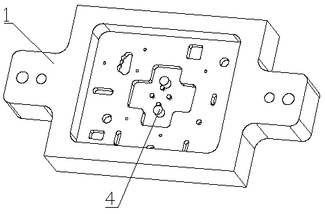
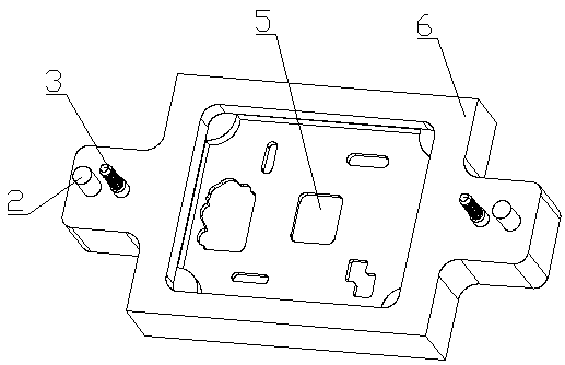
[0020] Such as Figure 1~Figure 3 As shown, a tooling for reflow soldering of cavity printed boards includes a lower cover 6 and an upper cover 1 of similar size, and the left and right sides of the lower cover 6 and the upper cover 1 are provided with corresponding left ears. and the right ear, the lower cover plate 6 and the upper cover plate 1 are provided with welding cavities, the lower cover plate 6 and the upper cover plate 1 are provided with a bottom plate in the welding cavity, and there are many holes for accommodating printed board components on the bottom plate A groove 5, the wall position of the welding cavity of the lower cover plate 6 is provided with a positioning step;

[0021] The left and right ears of the lower cover 6 are fixed with positioning pins 2 ...


PUM

PropertyMeasurementUnit
Diameteraaaaaaaaaa

Abstract

The invention relates to a tool for reflow welding of a cavity printed board. The tool comprises a lower cover plate and an upper cover plate which are equivalent in size, each of the lower cover plate and the upper cover plate is provided with a left lug and a right lug and a welding cavity, a bottom plate is arranged in each welding cavity, multiple grooves are formed in each bottom plate, and apositioning step is arranged in the welding cavity of the lower cover plate; the left lug and the right lug of the lower cover plate are fixed with positioning pins and provided with locking pin holes A, and corresponding positioning pin holes and locking pin holes B are formed in the upper cover plate; multiple adjusting holes are formed in the upper cover plate and positioned at the grooves, and an elastic adjusting member is mounted in each adjusting hole and comprises a base station, an adjusting knob and a spring pin; nail holes are formed in each base station which is fixed on the backof the upper cover plate through nails, a threaded hole is formed in the axis position of each base station, each adjusting knob is mounted in the corresponding threaded hole, and one end face of eachadjusting knob is positioned outside the corresponding base station while the other end face of the same is provided with the corresponding spring pin and positioned inside a cavity. The tool has theadvantages of high welding quality and high mass production consistency.

Description

technical field [0001] The invention relates to the field of soldering technology, in particular to a tooling for reflow soldering of cavity printed boards. Background technique [0002] At present, for the welding of cavity printed boards, it is mainly achieved by printing solder paste between the printed board and the cavity, supplemented by a medium-weight iron block, and then placing it on a hot plate for heating and welding to achieve the connection between the cavity and the cavity. The purpose of PCB soldering. [0003] However, there are problems: using iron blocks to adjust the pressure on the printed board will cause the printed board and the cavity surface to be unable to fit tightly, and it is easy to cause excessive welding voids; The welding of the whole body causes the welding environment to be uncontrollable, the welding quality cannot be guaranteed, the batch production consistency is poor, and the production efficiency is low. Contents of the invention ...

Claims


Application Information

Patent Timeline
IPC IPC(8): H05K3/00H05K3/34
CPCH05K3/0008H05K3/3494H05K2203/043
Inventor 陈亿雷宇鸣
Owner CHENGDU JINJIANG ELECTRONICS SYST ENG
Why Eureka
Try Eureka