
Damper device

A damper device and heater technology, which is applied in the direction of household refrigeration devices, cooling fluid circulation devices, lighting and heating equipment, etc., can solve the problems of heater lead wire falling off, disconnection, and time-consuming, etc., and achieve the effect of reliable fixing

Active Publication Date: 2015-11-11
NIDEC SANKYO CORP
View PDF12 Cites 2 Cited by
  • Summary
  • Abstract
  • Description
  • Claims
  • Application Information

AI Technical Summary

Problems solved by technology

However, when the lead wire for the heater is connected to the heater, the lead wire for the heater may be pulled and disconnected.
However, in the case of fixing the lead wire for the heater to the case with tape, it takes a lot of man-hours and there is a problem that the lead wire for the heater comes off when the tape is peeled off.

Method used


Image

  • Damper device
  • Damper device
  • Damper device

Examples


Embodiment Construction

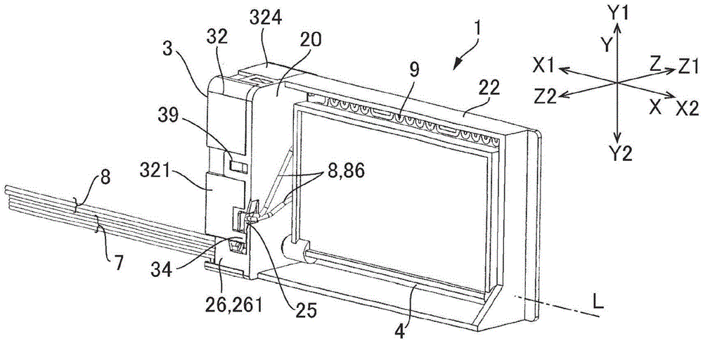
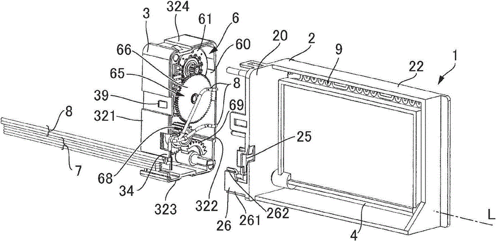
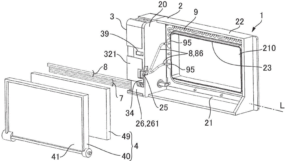
[0058] Hereinafter, a damper device for a refrigerator to which the present invention is applied will be described with reference to the drawings. In the following description, let the rotation center axis of the baffle 4 be L, let the direction along the rotation center axis L be the X direction, let the direction facing the opening be the Z direction, and let the direction perpendicular to the X direction and the Z direction be The direction will be described as the Y direction. And, let one side of the X direction be X1, the other side of the X direction be X2, one side of the Y direction be Y1, the other side of the Y direction be Y2, one side of the Z direction be Z1, and The other side in the Z direction will be described as Z2.

[0059] (the whole frame)

[0060] Fig. 1 (a), Fig. 1 (b) and Fig. 1 (c) are the perspective views of the damper device 1 applied to the present invention observed from the side where the baffle plate 4 is configured, and Fig. 1(a) is the damp...


PUM


Abstract

A damper device can easily and reliably lead bearing heater connected with a heater. In the air door device (1), the heater wire (8) through the formation of heater on the bulkhead plate (20) of the lead pathway (25) and pulled around to the driving chamber (60) side. And the heater wire (8) the middle part on the surface of the shell (3) of the housing (3) of the side plate portion (321) surface and formed on the bulkhead plate (20) the next plate side lead support department (26) is supported. Heater wire (8) along the bottom of the side plate (3) the Housing Department 321 outer surface (concavity (33) (330) along the X direction extension, the next plate side supporting leads the Ministry (26) for supporting a heater wire (8) along the side (321) outer surface extending part.

Description

technical field [0001] The present invention relates to a damper device used for cold air passages of refrigerators and the like. Background technique [0002] For a damper device used in a cold air passage of a refrigerator, for example, a structure in which a shutter is driven by a shutter driving mechanism to open and close an opening formed in a frame has been proposed (see Patent Documents 1 and 2). In addition, if the water condensed around the opening freezes, the frame and the flap are adsorbed by freezing, and the flap cannot be driven in the opening direction. Therefore, it has been proposed to provide a rectangular frame-shaped heater around the opening of the frame (see Patent Documents 1 and 2). [0003] Patent Document 1: Japanese Patent Application Laid-Open No. 7-19709 [0004] Patent document 2: Chinese utility model announcement number CN201973990U [0005] Like the damper devices described in Patent Documents 1 and 2, when a heater is installed, it is n...

Claims


Application Information

Patent Timeline
IPC IPC(8): F25D17/04
Inventor 齐藤俊二
Owner NIDEC SANKYO CORP
Learn More