Electric welding device

A screw-shaped, sliding block technology, applied in the direction of electrode support device, arc welding equipment, electrode characteristics, etc., can solve the problems of low welding efficiency, low efficiency, pollution, etc., achieve simple structure, improve welding efficiency, installation and disassembly convenient effect

Inactive Publication Date: 2018-06-29
CIXI ZHIJIANG MECHANICAL TECH CO LTD
View PDF0 Cites 0 Cited by
  • Summary
  • Abstract
  • Description
  • Claims
  • Application Information

AI Technical Summary

Problems solved by technology

[0002] When welding two pipe fittings, workers need to hold electric welding machines to weld them. In order to prevent the interface from touching the ground and polluting, it is necessary to wait for one side of the interface to cool down and then flip the pipe fittings to weld on the other side. This welding method is inefficient. Time-consuming and labor-intensive, and the existing special welding machines for pipe fittings are generally for large pipe fittings, and some welding machines for small pipe fittings only have one welding gun head, and the welding efficiency is not high

Method used


Image

  • Electric welding device
  • Electric welding device
  • Electric welding device

Examples


Embodiment Construction

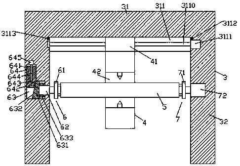
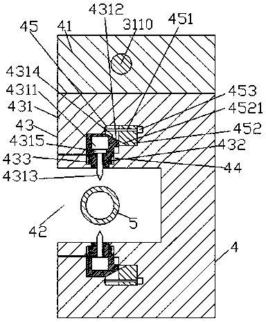
[0021] Such as figure 1 , figure 2 and image 3 As shown, an electric welding device of the present invention includes a frame body 3 composed of a cross bar 31 and support feet 32 ​​fixed on the left and right bottoms of the cross bar 31, and a sliding groove is provided in the end surface of the bottom of the cross bar 31 311, the sliding groove 311 is provided with a first spiral rod 3110 extending left and right, the first spiral rod 3110 is connected with a sliding block 41 in a spiral fit, and the bottom of the sliding block 41 is provided with an electric welding device 4, The front end of the electric welding device 4 is provided with a sinking groove 42, and the electric welding device 4 on the upper and lower sides of the sinking groove 42 is correspondingly provided with a first sliding chamber 43, and the first sliding chamber 43 is far away from the sinking groove One side of 42 is provided with a second sliding cavity 45 extending to the right side and is conn...


PUM


Abstract

The invention discloses an electric welding device. The electric welding device comprises a frame composed of a transverse rod and supporting legs fixed to the bottoms of the left and right sides of the transverse rod. A sliding groove is formed in the end face of the bottom of the transverse rod. A first screw rod extending left and right is arranged in the sliding groove. A sliding block is in screw-thread fit with the first screw rod. An electric welding device body is arranged at the bottom of the sliding block. A sunken groove is formed in the front end of the electric welding device body. First sliding cavities are formed in the portions, located on the upper and lower sides of the sunken groove, of the electric welding device body correspondingly. A second sliding cavity extending rightwards and communicating with each first sliding cavity is formed in the side, far from the sunken groove, of the first sliding cavity. A second screw rod extending left and right is arranged in each second sliding cavity. A push block is connected to each second screw rod in a screw-thread fit mode. A limiting block is arranged on the side, close to the sunken groove, of each first sliding cavity. A longitudinal sliding block is connected to the interior of each first sliding cavity in a screw-thread fit mode. The electric welding device is simple in structure, convenient to install and dismantle, high in welding efficiency and capable of meeting the requirements for welding of pipe fittings with different diameters.

Description

technical field [0001] The invention relates to the technical field of welding, in particular to an electric welding device. Background technique [0002] When welding two pipe fittings, workers need to hold electric welding machines to weld them. In order to prevent the interface from touching the ground and polluting, it is necessary to wait for one side of the interface to cool down and then flip the pipe fittings to weld on the other side. This welding method is inefficient. It is time-consuming and labor-intensive, and the existing special welding machines for pipe fittings are generally for large pipe fittings, and some welding machines for small pipe fittings have only one welding gun head, and the welding efficiency is not high. Contents of the invention [0003] The technical problem to be solved by the present invention is to provide an electric welding device, which can solve the above-mentioned problems in the prior art. [0004] The present invention is achie...

Claims


Application Information

Patent Timeline
Patent Type & Authority Applications(China)
IPC IPC(8): B23K9/173B23K9/28
CPCB23K9/173B23K9/28
Inventor 刘建华
Owner CIXI ZHIJIANG MECHANICAL TECH CO LTD
Why Eureka
Try Eureka