
Medical garbage treatment equipment with convenient cleaning effect

A technology for processing equipment and medical waste, applied in grain processing, cleaning hollow objects, cleaning methods and utensils, etc., can solve the problems of inconvenient cleaning, lack of automatic cleaning, etc., and achieve the effect of convenient operation, saving manpower, and good cleaning effect

Inactive Publication Date: 2018-06-29
ZHENGZHOU AIBOER MEDICAL EQUIP
View PDF0 Cites 10 Cited by
  • Summary
  • Abstract
  • Description
  • Claims
  • Application Information

AI Technical Summary

Problems solved by technology

[0005] The purpose of the present invention is: in order to solve the technical problem of inconvenient cleaning caused by the lack of automatic cleaning function of the existing medical waste disposal equipment, the present invention provides a medical waste disposal equipment that is easy to clean

Method used


Image

  • Medical garbage treatment equipment with convenient cleaning effect
  • Medical garbage treatment equipment with convenient cleaning effect

Examples


Embodiment 1

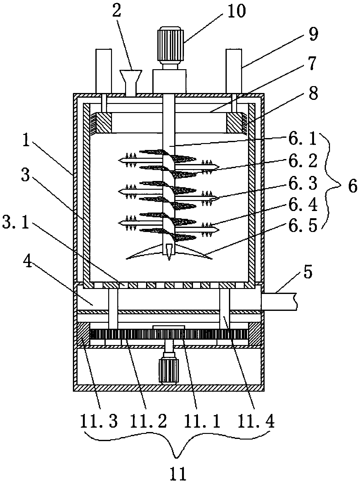
[0019] Such as Figures 1 to 2 As shown, this embodiment provides a medical waste treatment device that is easy to clean, including a housing 1, a feeding pipe 2 is arranged on the top of the housing 1, a rotating cylinder 3 with an upper end opening is arranged inside the housing 1, and the bottom of the rotating cylinder 3 is A number of through holes 3.1 are opened, and the housing 1 is provided with a waste material collection chamber 4 located below the rotating cylinder 3. Mechanism 6, the rotating cylinder 3 is provided with an annular block 7 that cooperates with the crushing mechanism 6, the crushing mechanism 6 is in the inner circle space of the annular block 7, and the outer circular surface of the annular block 7 is provided with a number of ring blocks that are in contact with the inner wall of the rotating cylinder 3 bristles 8, the top of the housing 1 is provided with two telescopic cylinders 9 arranged symmetrically with the center of the annular block 7, and...

Embodiment 2

[0022] Such as figure 1 As shown, this embodiment is further optimized on the basis of Embodiment 1. Specifically, the crushing mechanism 6 includes a stirring shaft 6.1, and the stirring shaft 6.1 is connected to a drive motor 10 arranged on the top of the housing 1. The stirring shaft 6.1 is provided with a spiral stirring piece 6.2 and a number of crushing blades 6.3, the crushing blades 6.3 and the spiral stirring pieces 6.2 are arranged alternately, and the upper and lower surfaces of all the crushing blades 6.3 are provided with a number of evenly distributed serrations 6.4, and the stirring shaft 6.1 The bottom is provided with a number of uniformly distributed downward-curved stirring blades 6.5.

[0023] In this embodiment, the combined mechanism of the helical stirring member, the crushing blade and the sawtooth in the crushing mechanism has a good crushing effect on medical waste and high working efficiency.

Embodiment 3

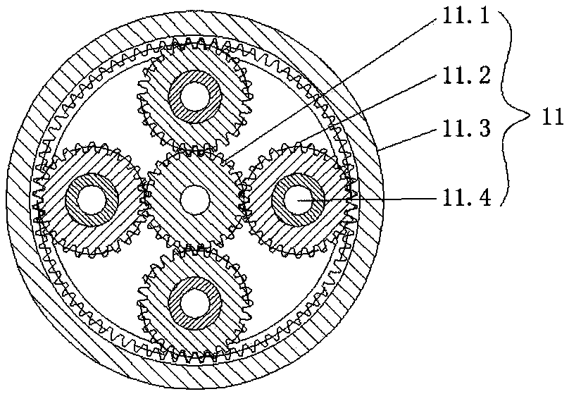
[0025] Such as Figures 1 to 2 As shown, this embodiment is further optimized on the basis of Embodiment 1. Specifically, the bottom of the rotating drum 3 is connected with a gear transmission mechanism 11 located below the waste collection chamber 4 for driving the rotating drum 3 to rotate. , the gear transmission mechanism 11 includes a center wheel 11.1, and the center wheel 11.1 is meshed with a number of planetary wheels 11.2 uniformly distributed around the center wheel 11.1. 11.2 is located on the ring gear of the inner gear cylinder 11.3, and the center of each planetary gear 11.2 is provided with a rotating shaft 11.4, and each rotating shaft 11.4 is movably connected with the bottom of the rotating cylinder 3.


PUM


Abstract

The invention discloses medical garbage treatment equipment with convenient cleaning effect, and relates to the technical field of medical garbage treatment equipment. The medical garbage treatment equipment comprises a casing, wherein a material charge pipe is arranged at the top part of the casing; a rotary cylinder with an upper opening is arranged in the casing; a plurality of through holes are formed in the bottom part of the rotary cylinder; a waste collection cavity is arranged in the casing, is positioned under the rotary cylinder, and is connected with a material discharge pipe; a stirring and crushing mechanism is arranged in the rotary cylinder and is connected with the top part of the casing; an annular block is arranged in the rotary cylinder and is matched with the stirring and crushing mechanism; the stirring and crushing mechanism is arranged in an inner circle space of the annular block; a plurality of brush hairs are arranged at the peripheral surface of the annular block and are in contact with the inner wall of the rotary cylinder; two telescopic air cylinders are symmetrically arranged at the top part of the casing by using the annular block as the center; a piston rod of each telescopic air cylinder is connected with the top part of the annular block. The medical garbage treatment equipment has the advantages that the operation is simple, the cleaning is convenient, and the environment-friendly property is high.

Description

technical field [0001] The invention relates to the technical field of medical waste disposal equipment, and more particularly relates to a medical waste disposal equipment that is easy to clean. Background technique [0002] Medical waste refers to the polluting waste produced by the hospital that has been in contact with the patient's blood, body, etc., such as used cotton balls, gauze, adhesive tape, waste water, disposable medical equipment, postoperative waste products, and expired medicines. etc. According to the medical inspection report of the national health department, because medical waste has the characteristics of space pollution, acute infection and latent pollution, its viruses and germs are dozens, hundreds or even thousands of times more harmful than ordinary domestic waste. Improper use will cause serious pollution to the environment and may also become the source of epidemics. The treatment technology of medical waste is still in the exploratory stage in...

Claims


Application Information

Patent Timeline
Patent Type & Authority Applications(China)
IPC IPC(8): B02C18/10B02C18/18B02C18/24B02C18/16B02C23/16B08B9/087
CPCB02C18/0092B02C18/10B02C18/16B02C18/18B02C18/24B02C23/16B02C2023/165B02C2201/06B08B9/0808
Inventor 曹清峰
Owner ZHENGZHOU AIBOER MEDICAL EQUIP
Learn More