
Placement type probe and visual quantitative evaluation method for damage detection of metal component

A metal component, damage detection technology, applied in the direction of measuring devices, material magnetic variables, instruments, etc., can solve rare problems, and achieve the effect of increasing the detection rate and improving the detection efficiency

Active Publication Date: 2018-06-22
XI AN JIAOTONG UNIV
View PDF5 Cites 7 Cited by
  • Summary
  • Abstract
  • Description
  • Claims
  • Application Information

AI Technical Summary

Problems solved by technology

At present, there are few studies on pulsed eddy current detection probes and detection methods for damage such as metal component delamination, cracks and corrosion, and pulsed eddy current detection probes and detection methods that can achieve accurate, rapid positioning and quantitative evaluation of metal component delamination, cracks and corrosion damage not yet seen

Method used


Image

  • Placement type probe and visual quantitative evaluation method for damage detection of metal component
  • Placement type probe and visual quantitative evaluation method for damage detection of metal component
  • Placement type probe and visual quantitative evaluation method for damage detection of metal component

Examples


Embodiment Construction

[0029] The present invention will be described in further detail below in conjunction with the accompanying drawings and specific embodiments.

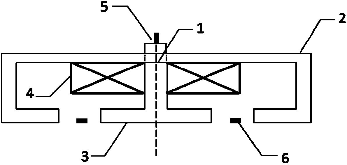
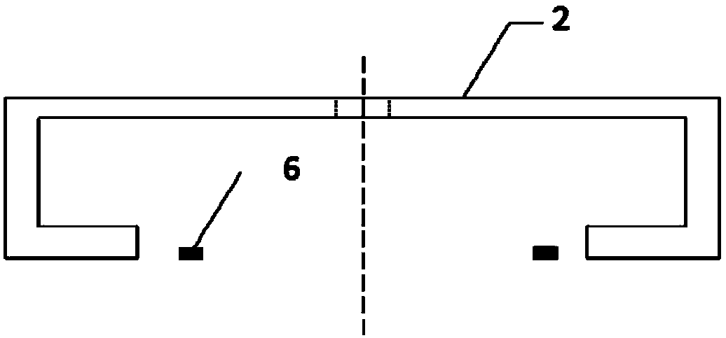
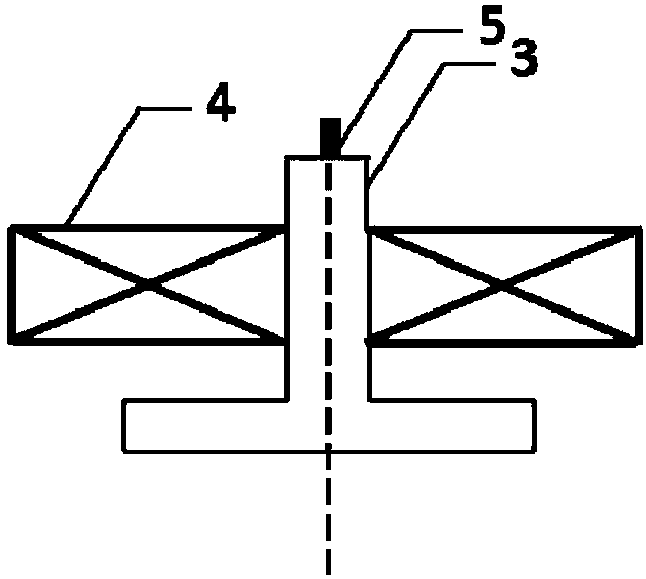
[0030] Such as figure 1 , figure 2 , image 3 , Figure 4As shown, the placement probe for metal component damage detection of the present invention includes a magnetization gathering core group 1, a disc excitation coil 4 fixed on the magnetism gathering core group 1, a vertical magnetic field gradient sensor 5 and a group of annular distributed magnetic fields Gradient sensor array6. The magnetic gathering core group 1 is composed of a non-closed "mouth" shaped cylindrical core 2 at the bottom center of the axial section and a cylindrical magnetic core 3 with a "⊥" shaped axial section, and the two cylindrical magnetic cores are coaxial; the disc type The excitation coil 4 is coaxial with the magnetic core group 1; the vertical magnetic field gradient sensor 5 is located at the top of the "⊥"-shaped cylindrical magnetic core 3;...


PUM


Abstract

The invention discloses a placement type probe and a visual quantitative evaluation method for damage detection of a metal component. The placement type probe comprises a magnetism gathering magneticcore group, a disc-type exciting coil, a vertical magnetic field gradient sensor and a group of magnetic field gradient sensor arrays which are distributed annularly; the magnetism gathering magneticcore group consists of a cylindrical magnetic core of which the bottom centre of the axial cross section is a non-closed mouth shape and a cylindrical magnetic core of which the axial cross section isan inverted T shape; the two cylindrical magnetic cores are coaxial; the disc-type exciting coil and the magnetism gathering magnetic core group are coaxial; the vertical magnetic field gradient sensor is positioned at the top of the inverted T-shaped cylindrical magnetic core; the magnetic field gradient sensor arrays which are distributed annularly are uniformly arranged at the bottom of a gapbetween the cylindrical magnetic core of which the bottom centre of the axial cross section is the non-closed mouth shape and the cylindrical magnetic core of which the axial cross section is the inverted T shape. The invention also provides a method for implementing damage detection and visual quantitative evaluation of a metal component by applying the probe; quick and high-precise detection, imaging and quantitative evaluation can be performed on the metal component; the placement type probe and the visual quantitative evaluation method for the damage detection of the metal component have an important engineering application value.

Description

technical field [0001] The invention belongs to the technical field of non-destructive testing, and relates to a placed probe for damage testing of metal components and a visual quantitative evaluation method. Background technique [0002] In order to realize the long-term safe operation of large and complex structures and equipment, the research and development of related theories and technologies for structural safety maintenance is very important. Non-destructive testing technology is to detect and quantitatively analyze the damage of the structure of the object under test according to the change of the physical characteristics of the object under the premise of not damaging the structure of the object under test, which is the basis of structural safety assessment and maintenance technology. Now, non-destructive testing technology has become one of the indispensable key technologies in the engineering field, and is widely used in petroleum, chemical, energy, transportatio...

Claims


Application Information

Patent Timeline
IPC IPC(8): G01N27/90
CPCG01N27/9046
Inventor 李勇任淑廷陈振茂闫贝王翼
Owner XI AN JIAOTONG UNIV
Learn More