
Universal chassis of paddy field working device driven with hydrostatic drive

A technology of hydrostatic drive and working device, applied in the field of agricultural machinery, can solve the problems of inability to realize infinitely variable speed change, complex and bulky transmission system, not meeting the requirements of light weight, etc., and achieves improved passability, good fuel economy, and flexibility. Effect

Active Publication Date: 2018-06-22
NANJING AGRI MECHANIZATION INST MIN OF AGRI
View PDF11 Cites 4 Cited by
  • Summary
  • Abstract
  • Description
  • Claims
  • Application Information

AI Technical Summary

Problems solved by technology

Most of the existing paddy field mechanical chassis are traditional mechanical chassis, which can basically meet the requirements of paddy field work, but also have the following disadvantages: 1) Multi-stage gear transmission and shifting mechanism are used for transmission, the transmission system is complex and heavy, and the layout is fixed and single. Infinitely variable speed cannot be realized; 2) The power density is low, which does not meet the requirements of lightweight, and the speed regulation range is small; 3) The turning radius is large, which is not conducive to turning around; 4) The braking system is complicated, and a special friction braking device needs to be installed; 5 ) The impact load is large during shifting, starting and acceleration; 6) It is not conducive to the realization of automatic intelligent control, and remote control is difficult

Method used


Image

  • Universal chassis of paddy field working device driven with hydrostatic drive
  • Universal chassis of paddy field working device driven with hydrostatic drive
  • Universal chassis of paddy field working device driven with hydrostatic drive

Examples


Embodiment Construction

[0024] The present invention will be further described below in conjunction with the accompanying drawings and specific embodiments.

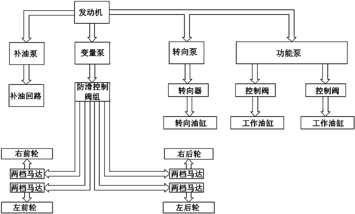
[0025] figure 1 Shown is the power transmission roadmap of the present invention, which mainly consists of three parts: 1) the traveling mechanism driven by the swash plate type bidirectional variable-variable plunger pump; 2) the steering mechanism powered by the gear pump; 3) the gear pump powered Source load-sensitive multi-actuator working mechanism.

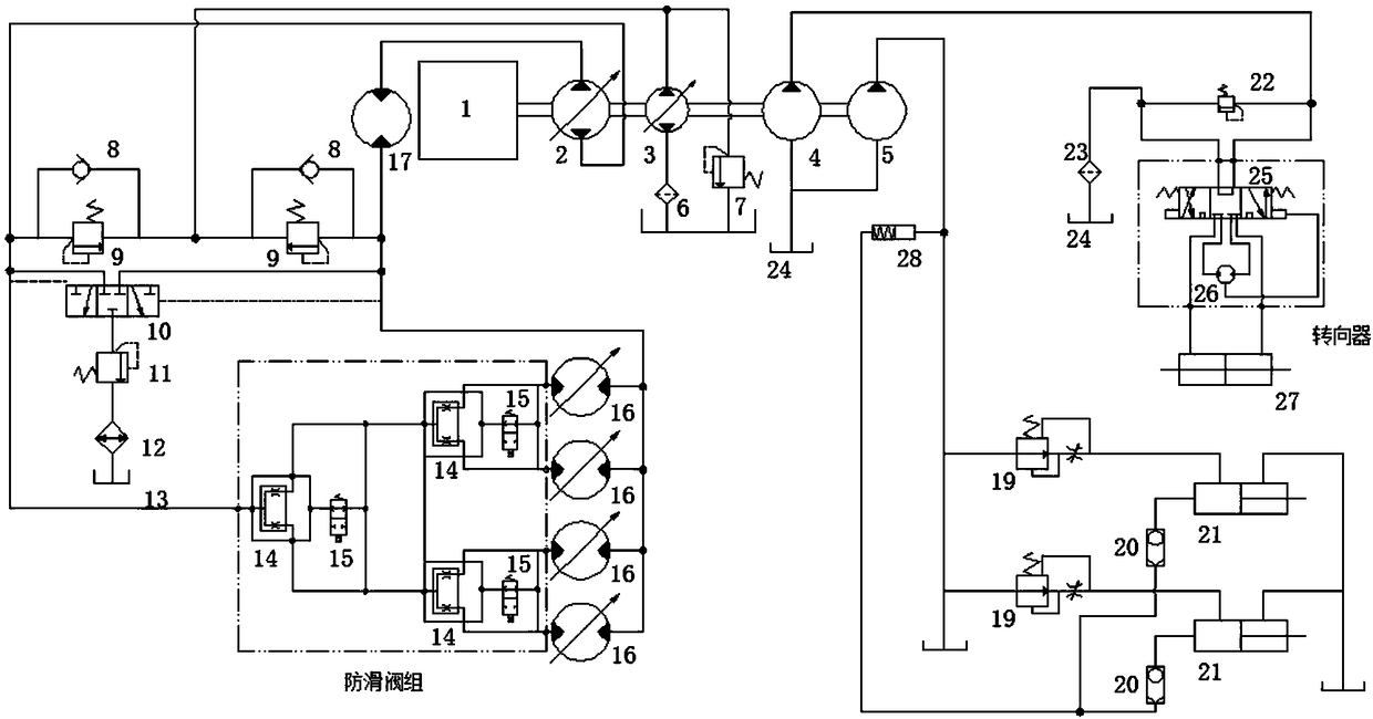
[0026] The engine 1 is the power source of the whole system, which transmits the power to the two-way variable plunger pump and two gear pumps respectively through the connecting device. The valve group is connected with four two-stage variable travel motors. The two-way variable plunger pump itself has the dual functions of adjusting flow and changing flow direction, and can continuously adjust the speed and direction of the output shaft. The two-stage variable motor changes its displacemen...


PUM


Abstract

The invention relates to a universal chassis of a paddy field working device with a hydrostatic drive. A variable displacement piston pump is connected with an engine, the oil output port of the variable displacement piston pump is connected with four variable displacement motors through an anti-slip control valve group, and respective output shafts of the four variable displacement motors are connected with wheels through respective hub reduction gears; a steering system comprises a steering pump, the oil output port of the steering pump is connected with a steering device, and the steering device is connected with a steering oil cylinder; a functional pump of a functional working mechanism is connected with the engine, and the oil output port of the functional pump is connected with at least two working oil cylinders through a control member; the control member comprises a pressure compensation valve, a flow control valve and a shuttle valve, it is ensured by the pressure compensation valve that the amount of the flow passing through a variable throttle is proportional to the opening size, a spring bias pressure is set by the flow control valve to cooperatively regulate the outlet pressure of the pump with the maximum load, and the maximum loading pressure of at least two execution members is transmitted to a spring cavity of the flow control valve by the shuttle valve.

Description

technical field [0001] The invention relates to a general chassis of a paddy field working device, in particular to a general chassis of a hydrostatically driven paddy field working device, which belongs to the technical field of agricultural machinery. Background technique [0002] Paddy fields are planted in a large area in southern my country, and rice is one of the most important staple foods. Ensuring increased production and income of paddy field crops is of great significance to maintaining food supply and ensuring national food security. However, the rheological soil characteristics of paddy fields are complex, the mud foot depth is large, and the working environment is harsh. These unfavorable factors have increased the labor intensity of farmers and reduced operating efficiency. [0003] Paddy field machinery has been working in paddy fields with complex soil characteristics and deep mud footing for a long time. It is necessary to ensure its normal driving and oper...

Claims


Application Information

Patent Timeline
Patent Type & Authority Applications(China)
IPC IPC(8): A01B51/02
CPCA01B51/02
Inventor 扈凯张文毅余山山祁兵纪要李坤严伟
Owner NANJING AGRI MECHANIZATION INST MIN OF AGRI
Learn More