Flexible multi-state switch and control method thereof
A control method and multi-state technology, applied to AC network circuits, electrical components, and AC networks with the same frequency from different sources, etc., can solve the problems of AC system frequency instability, limited number of switches, discrete adjustments, etc., to achieve control The method is flexible and diverse, the control is continuous, and the effect of avoiding power supply interruption
- Summary
- Abstract
- Description
- Claims
- Application Information
AI Technical Summary
Problems solved by technology
Method used
Image


Examples
Embodiment 1
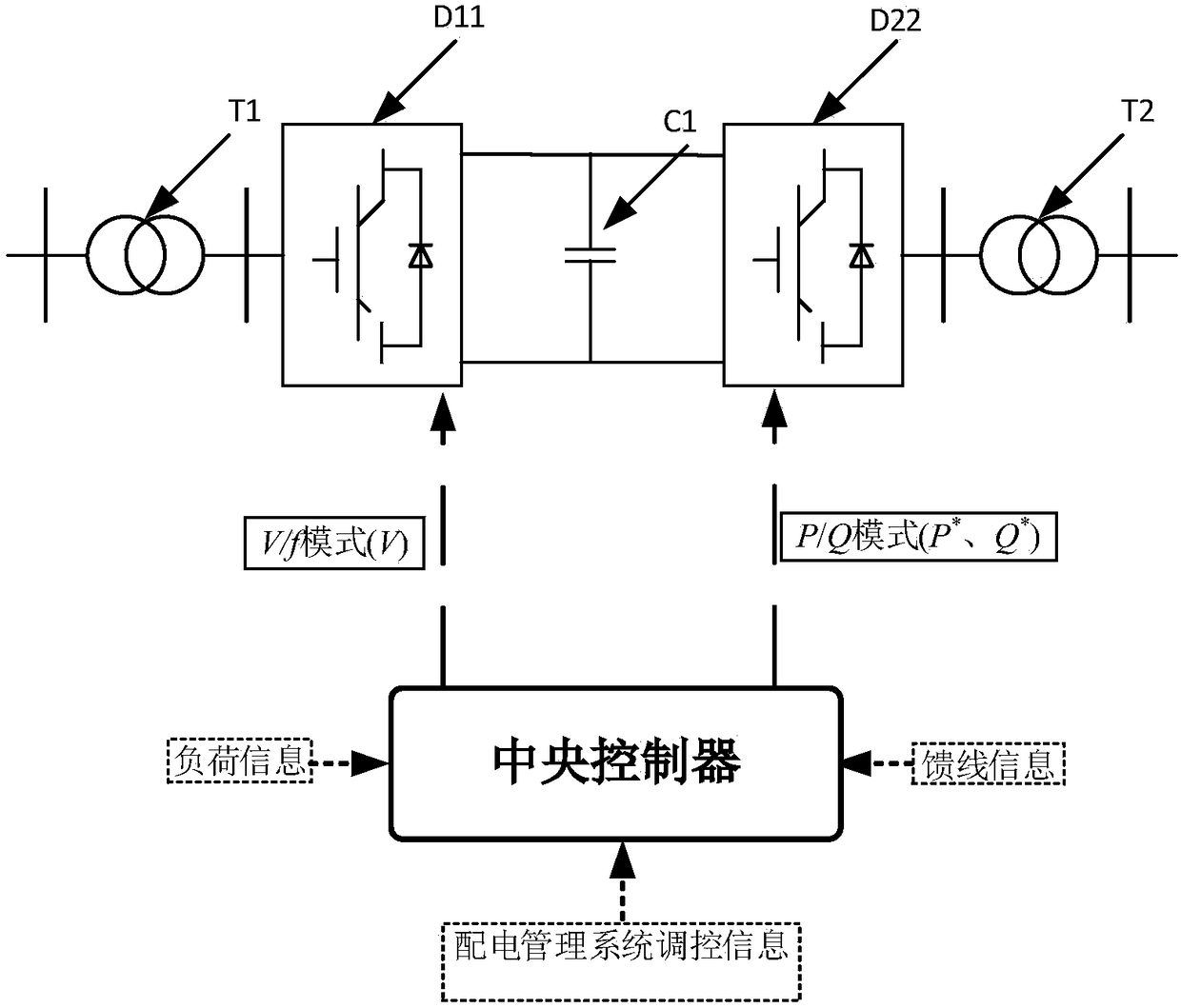
[0048] Such as Figure 9 As shown, as a power electronic converter, the flexible multi-state switch of the present invention is connected between the first feeder K11 and the second feeder K22. Such as figure 1 As shown, the flexible multi-state switch of the present invention includes: a first isolation transformer T1, a second isolation transformer T2, a first controlled voltage source D11, a second controlled voltage source D22, a DC bus stabilizing capacitor C1 and a central controller. The first controlled voltage source D11 is connected to the second controlled voltage source D22 through the DC bus capacitor C1. The first feeder K11 is connected to the first controlled voltage source D11 through a first isolation transformer T1; the second feeder K22 is connected to the second controlled voltage source D22 through a second isolation transformer T2. One end of the central controller is connected to the voltage and current sampling and detection sensor, and the other end...
Embodiment 2
[0054] Such as Figure 6 As shown, this embodiment includes the first flexible multi-state switch A1, the second flexible multi-state switch A2, the third flexible multi-state switch A3, the fourth flexible multi-state switch A4...the nth flexible multi-state switch An, n≥ 3. The first substation B1, the second substation B2, the third substation B3...the mth substation Bm, where m≥3. The first substation B1 is connected to the second substation B2 through the second flexible multi-state switch A2, and is connected to the third substation B3 through the third flexible multi-state switch A3. The third substation B3 is connected to other substations through the fourth flexible multi-state switch A4. The mth substation Bm is connected to other substations through the nth flexible multi-state switch An. When the load of the first substation B1 is too large, the flexible multi-state switch can be used to provide active power support through the second substation B2 and the third ...
Embodiment 3
[0059] Such as Figure 7 As shown, this embodiment includes feeder K1, feeder K2, feeder K3, feeder K4, feeder K5, feeder K6, isolation transformer T1, isolation transformer T2, isolation transformer T3, isolation transformer T4, isolation transformer T5, isolation transformer T6, the first A controlled voltage source D1, a second controlled voltage source D2, a third controlled voltage source D3, a fourth controlled voltage source D4, a fifth controlled voltage source D5, a sixth controlled voltage source D6, and a DC bus capacitor C1, a DC bus capacitor C2, a DC bus capacitor C3, and a common DC bus. The feeder K1 is connected to the feeder K2 through the isolation transformer T1, the first controlled voltage source D1, the DC bus capacitor C1, the second controlled voltage source D2, and the isolation transformer T4, and the feeder K1, the isolation transformer T1, and the first controlled voltage source D1 , DC bus capacitor C1, second controlled voltage source D2, isolat...
PUM
 Abstract
Description
Claims
Application Information
 - R&D
- Intellectual Property
- Life Sciences
- Materials
- Tech Scout
- Unparalleled Data Quality
- Higher Quality Content
- 60% Fewer Hallucinations
Browse by: Latest US Patents, China's latest patents, Technical Efficacy Thesaurus, Application Domain, Technology Topic, Popular Technical Reports.
© 2025 PatSnap. All rights reserved.Legal|Privacy policy|Modern Slavery Act Transparency Statement|Sitemap|About US| Contact US: help@patsnap.com