
Underground cable fault detection system and fault detection method thereof

A technology for fault detection and underground cables, applied in fault location, information technology support system, fault detection according to conductor type, etc., can solve the economic loss and social impact of residents' lives and factories and mines, and the difficulties and delays in the daily maintenance of deep-buried cables Quickly repair and restore the power transmission time and other problems, so as to reduce the test blind area, intuitive path finding results, and reduce the blind area

Active Publication Date: 2018-06-19
WUHAN UNIV OF SCI & TECH
View PDF9 Cites 35 Cited by
  • Summary
  • Abstract
  • Description
  • Claims
  • Application Information

AI Technical Summary

Problems solved by technology

However, compared with overhead open wires, the daily maintenance of deep buried cables is more difficult
During the long-term operation of underground power cables, failures are inevitable. The lack of corresponding equipment to detect fault points and delay the repair and restoration of power transmission time will not only cause power loss to power companies, but also bring significant economic benefits to residents and factories and mines. loss and social impact

Method used


Image

  • Underground cable fault detection system and fault detection method thereof
  • Underground cable fault detection system and fault detection method thereof
  • Underground cable fault detection system and fault detection method thereof

Examples


Embodiment Construction

[0057] The specific embodiments of the present invention will be described below with reference to the drawings.

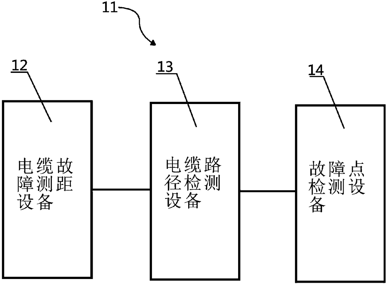
[0058] Such as figure 1 As shown, the underground cable fault detection system 11 includes: a cable fault distance measuring device 12, a cable path detection device 13 and a fault point detection device 14.

[0059] The three devices in the underground cable fault detection system 11 are selected from the following three devices to be combined: cable fault location equipment, high-voltage signal generator and signal receiver.

[0060] Cable fault location equipment includes: cable fault location equipment and high voltage signal generator combination.

[0061] The fault point detection equipment includes: a combination of a high-voltage signal generator and a signal receiver.

[0062] Cable path detection equipment includes: high-voltage signal generator and signal receiver combination.

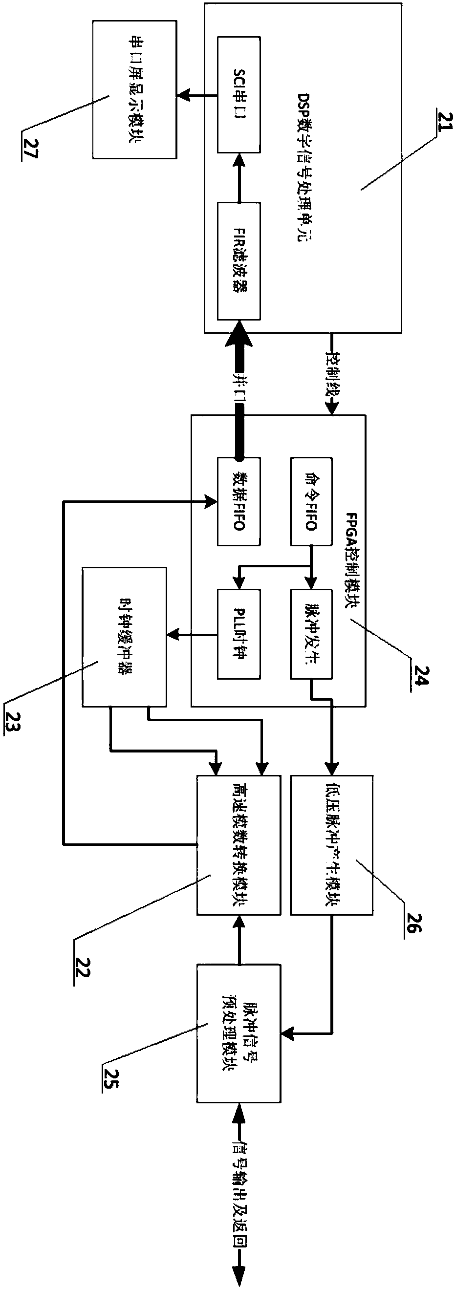
[0063] The cable fault location equipment 12 includes: a low-voltage pulse signal sour...


PUM


Abstract

The invention provides an underground cable fault detection system and fault detection method thereof. The underground cable fault detection system comprises a cable fault ranging device, a cable pathdetection device, and a fault point detection device. The cable fault ranging device consists of a low-voltage pulse signal source, a high-voltage pulse signal source, and a high-speed receiving device to realize signal detection in a low-voltage pulse reflection method and a flashover method. The cable path detection device includes an alternating-current high-voltage signal source and an electromagnetic induction receiving device; the frequency and amplitude of the alternating-current high-voltage signal source are adjustable; the alternating-current high-voltage signal source excites a to-be-detected cable to generate an electromagnetic field; and the electromagnetic induction receiving device detects the electromagnetic field generated by the to-be-detected cable. The fault point detection device includes a high-voltage pulse signal source, a direct-current signal source, an alternating-current signal source, a step-voltage receiving device, an electromagnetic induction receivingdevice, and an acousto-magnetic synchronous receiving device. The underground cable fault detection system can be applied to detection of underground cable open-circuit, short-circuit, grounding, low-resistance, high-resistance flashover and high-resistance leakage faults to obtain an accurate fault point.

Description

Technical field [0001] The invention relates to an underground cable fault detection system and a fault detection method thereof, belonging to the field of cable detection. Background technique [0002] As an important component of power transmission and distribution in the power system, power cables are widely used in urban power grids, internal power supply lines of industrial and mining enterprises, and underwater transmission lines that cross rivers and seas. However, compared with overhead open wires, the daily maintenance of deeply buried cables is more difficult. During the long-term operation of underground power cables, failures are inevitable. The lack of corresponding equipment to detect fault points and delays in rush repairs to restore power transmission time will not only cause power loss to power companies, but also bring significant economic benefits to residents and factories and mines. Loss and social impact. Therefore, how to quickly and accurately find the l...

Claims


Application Information

Patent Timeline
Patent Type & Authority Applications(China)
IPC IPC(8): G01R31/08
CPCG01R31/083Y04S10/52
Inventor 周凤星梅鸣阳汤健强马娅婕卢少武严保康但峰胡轶宁博文
Owner WUHAN UNIV OF SCI & TECH
Learn More