
Long-wave infrared Fourier transform imaging spectrometer athermalization relay imaging system

A Fourier transform, imaging spectrometer technology, applied in interference spectroscopy, color/spectral property measurement, instruments, etc., can solve the problems of optical passive heat dissipation in the long wave band, and achieve low processing cost, easy acquisition, and improved reliability. The effect of noise ratio

Active Publication Date: 2020-04-24
CHANGCHUN INST OF OPTICS FINE MECHANICS & PHYSICS CHINESE ACAD OF SCI
View PDF4 Cites 2 Cited by
  • Summary
  • Abstract
  • Description
  • Claims
  • Application Information

AI Technical Summary

Problems solved by technology

[0004] The present invention provides a long-wave infrared Fourier transform imaging spectrometer adiabatic relay imaging system to solve the special design requirements proposed by the optical imaging system based on the stepped mirror and the long-wave band optical passive athermal difference.

Method used


Image

  • Long-wave infrared Fourier transform imaging spectrometer athermalization relay imaging system
  • Long-wave infrared Fourier transform imaging spectrometer athermalization relay imaging system
  • Long-wave infrared Fourier transform imaging spectrometer athermalization relay imaging system

Examples


specific Embodiment approach 1

[0029] Specific implementation mode 1. Combination Figure 1 to Figure 9 Describe this embodiment, a long-wave infrared Fourier transform imaging spectrometer athermal difference relay imaging system, the imaging system uses a refraction-diffraction hybrid lens to achieve athermal difference, and realizes passive The adiabatic function adopts the object-space telecentric optical path, which matches the front telephoto system. The relative illuminance at the edge of the image plane is close to 85%, the distortion is less than 0.4%, the passivation value at 17lp / mm is close to the diffraction limit, and the depth of field of the system meets the total height of the stepped micro-mirror. , the maximum change rate of the system MTF value does not exceed 1.5%. The system achieves 100% cold stop matching without vignetting.

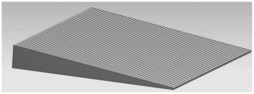
[0030] Ladder micromirror (object plane) 1, beam splitter 2, compensation plate 3, first lens 4, second lens 5, third lens 6, fourth lens 7 arranged in seque...


PUM

PropertyMeasurementUnit
thicknessaaaaaaaaaa
thicknessaaaaaaaaaa
thicknessaaaaaaaaaa

Abstract

The invention discloses a long-wave infrared Fourier transform imaging spectrometer athermalization relay imaging system, relates to the technical field of spectral imaging, and solves the defect of poor athermalization of the existing long-wave infrared optical system. The front surface of a first lens is a cylindrical mirror, a second lens is a refractive-diffractive hybrid lens, the front surface is a binary surface, the rear surface of a fifth lens is an even aspheric surface, and a beam splitter and a compensation plate are parallel flat plates. The beam splitter and the compensation plate are both made of zinc selenide, the first lens is a convex lens with positive diopter and is made of zinc selenide, the second lens is a convex lens with positive diopter and is made of germanium, the third lens and the fifth lens are convex lenses with positive diopter and are both made of zinc selenide, and the fourth lens is a concave lens with negative diopter. The relative illuminance of the edge of the image plane is greater than 85%, the distortion is less than 0.4%, the transmission value at the 171p / mm position is close to the diffraction limit, the depth of field of the system meets the total height of the stepped micro-reflector, and the maximum change rate of the MTF value of the system does not exceed 1.5% when different stepped height positions are taken as the object planefor imaging.

Description

technical field [0001] The invention relates to an optical passive athermal difference relay imaging system working in long-wave infrared and applied to a time-space joint modulation type Fourier transform imaging spectrometer based on stepped microreflectors. Background technique [0002] The optical passive athermalization method does not introduce additional mechanical structures. It only needs to combine different optical materials and use the difference in chromatic aberration coefficient and thermal difference coefficient to achieve complementarity. Passive athermalization can be realized. It has simple structure, low weight Light and other advantages. Therefore, most infrared optical systems choose this method to achieve athermalization. However, this method requires at least three kinds of materials to be combined with each other, and the long-wave infrared materials are limited by the level of domestic material preparation, and there are fewer types of materials th...

Claims


Application Information

Patent Timeline
Patent Type & Authority Applications(China)
IPC IPC(8): G01J3/45G01N21/35G01N21/01G01N25/20G02B1/00G02B13/00G02B13/14G02B13/18G02B13/22
CPCG01J3/45G01N21/01G01N21/35G01N25/20G01N2021/0112G02B1/00G02B13/0045G02B13/0055G02B13/008G02B13/14G02B13/18G02B13/22
Inventor 梁静秋任俊吕金光王惟彪秦余欣陶金赵百轩
Owner CHANGCHUN INST OF OPTICS FINE MECHANICS & PHYSICS CHINESE ACAD OF SCI
Learn More