
Forward tracking generation method and device for point cloud geodesic path

A path and forward technology, which is applied in the field of point cloud geodesic path forward tracking generation, can solve problems such as low accuracy, poor geodesic calculation accuracy, and failure to faithfully point cloud data

Active Publication Date: 2018-06-19
SOUTHWEAT UNIV OF SCI & TECH
View PDF5 Cites 7 Cited by
  • Summary
  • Abstract
  • Description
  • Claims
  • Application Information

AI Technical Summary

Problems solved by technology

(1) The method of relying on the point cloud normal: In the geodesic calculation process, the method that needs to use the point cloud normal has inherent defects, because the point cloud normal is unknown, and the normal of the target point cloud is required It is obtained by estimation, the normal estimation accuracy is not high, the normal direction cannot be globally consistent, and there is confusion, so the geodesic calculation accuracy is poor. (2) The method of cell division: in the process of sampling the physical model, the geometric Different shapes, different sampling densities
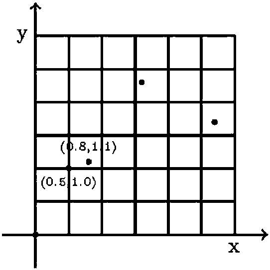
Flatter areas usually use larger intervals (lesser density), and curved parts use smaller intervals (greater density). Due to the anisotropy of sampling, the existing mesh homogenization methods are more accurate for point clouds. The cell division is continuously subdivided from large to small until the cell contains only one point cloud data point. This division is uniform (the spacing in the three directions of X, Y, and Z is equal), resulting in point cloud data points often located in Inside the cell, the position of the cell is used to replace the position coordinates of the data point. The final generated geodesic line hardly passes through any data point of the point cloud (the point cloud data is not on the geodesic line), which is not faithful to the point cloud. data, so a less precise calculation method

Method used

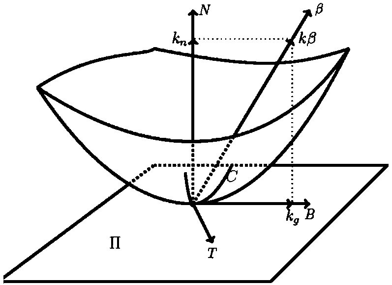
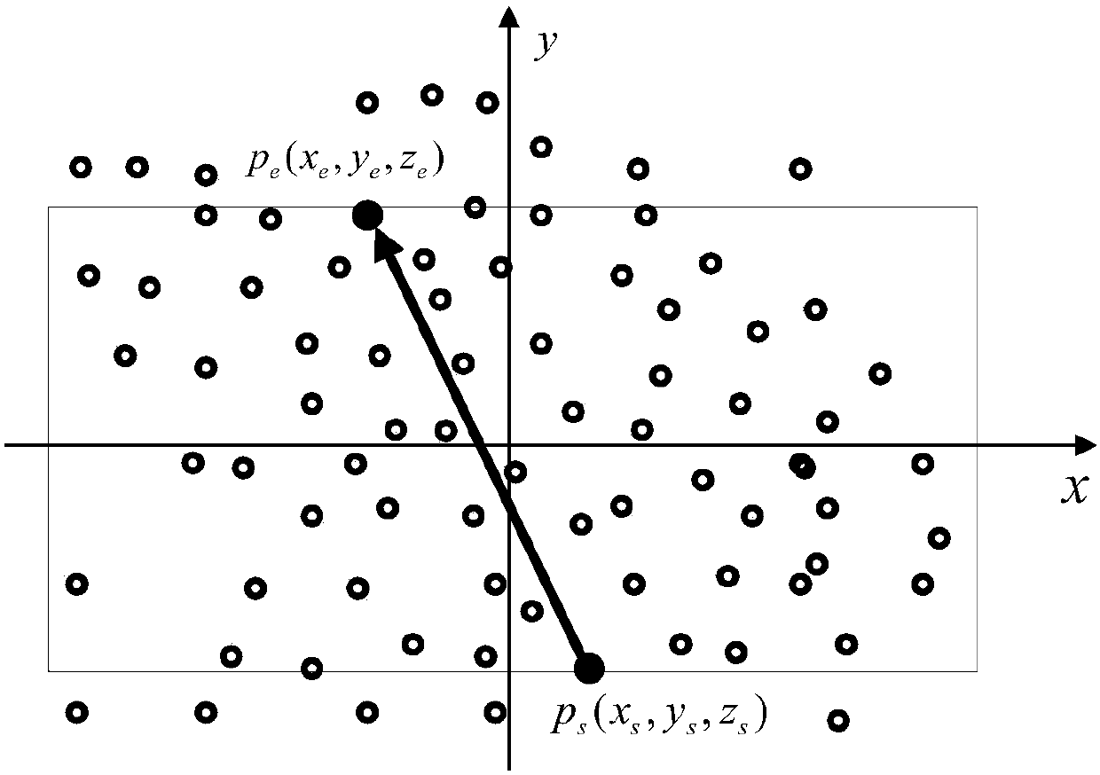

Image

  • Forward tracking generation method and device for point cloud geodesic path
  • Forward tracking generation method and device for point cloud geodesic path
  • Forward tracking generation method and device for point cloud geodesic path

Examples


Embodiment Construction

[0139] All features disclosed in this specification, or steps in all methods or processes disclosed, can be combined in any way, except for mutually exclusive features and / or steps.

[0140] Any feature disclosed in this specification, unless specifically stated, can be replaced by other equivalent or alternative features with similar purpose. That is, unless expressly stated otherwise, each feature is one example only of a series of equivalent or similar features.

[0141] 1. Basic background of the present invention:

[0142] 1.1 Fast Marching Method (fast marching method)

[0143] Fast Marching Method (abbreviation: FMM) is a numerical method that calculates the time when the interface expands in the normal direction of the grid and reaches each grid point by solving the Eikonal Equation boundary value problem. FMM is widely used in computer graphics, image processing and other research fields. The Eikonal Equation is as follows:

[0144]

[0145] where F(x)≥0 is the...


PUM


Abstract

The invention relates to the field of point cloud data processing. A main traveling direction between a start point ps(xs,ys,zs) and an end point pe (xe,ye,ze) of the geodesic path is selected, and agridding area is determined by the main traveling direction; coordinate values of all data points in the gridding area are extracted, three coordinate component arrays are formed, the arrays are sorted, the same coordinate component values are removed, and maximum and minimum values of the coordinates of all point cloud data points in the gridding area are found; step sizes hxi, hyj and hzk of thedata points in three axial directions are calculated respectively, the data points between the two points ps and pe are subjected to non-uniformly gridding, and the step 3 is executed; arrival time of each cell in the wavefront grid is calculated by UNCDFMM according to the step sizes hxi, hyj and hzk; the cells meeting the approximate geodesic property are screened out after the arrival time ofeach cell is calculated, and vertices of the cells are sequentially connected to form the geodesic path.

Description

technical field [0001] The invention relates to the field of point cloud data processing, in particular to a point cloud geodesic path forward tracking generation method and device. Background technique [0002] The shortest line between two points measured on the Earth's surface containing the two points to be measured. A geodesic, also known as a geodesic or geodesic, can be defined as the shortest or longest path between two points in space. [0003] Airline: The navigation of an airplane or ship in life is a geodesic. [0004] The geodesic on the cylinder: cut and flatten the cylindrical surface, which gives an equidistant transformation from the cylindrical surface to the plane, and the geodesic of the plane is a straight line. Therefore, the geodesic on the cylindrical surface: roll the plane into a cylinder Surface, the curves transformed from the straight line on the plane, it is easy to find that they are straight lines (sub-generic lines of the cylindrical surfac...

Claims


Application Information

Patent Timeline
IPC IPC(8): G01C21/34
CPCG01C21/3446
Inventor 李自胜肖晓萍
Owner SOUTHWEAT UNIV OF SCI & TECH
Learn More