
Head of pantograph

A pantograph and bow head technology, which is applied in the field of electric traction locomotives, can solve the problems such as the unevenness of the contact line of the skateboard and the wear of the skateboard, the inconvenience of locomotive operation, maintenance and repair, and the arc discharge of the pantograph, so as to reduce the horizontal mechanical The effect of friction and wear, reducing the phenomenon of arc discharge and reducing arc wear

Active Publication Date: 2018-06-19
ZHUZHOU ELECTRIC LOCOMOTIVE CO
View PDF10 Cites 3 Cited by
  • Summary
  • Abstract
  • Description
  • Claims
  • Application Information

AI Technical Summary

Problems solved by technology

The local unevenness of the skateboard intensifies the dynamic effect between the pantograph and catenary, that is, when the skateboard and the contact line slide relative to each other, strong impact phenomena such as jumping off-line between the pantograph and catenary are likely to occur at the local concave and convex defects of the skateboard, resulting in arc discharge between the pantograph and catenary. As a result, arcing and arcing wear are caused. Under the dual effects of mechanical friction and wear and arcing and arcing wear, it will aggravate the local unevenness of the skateboard and the wear of the contact line and the skateboard, so that the pantograph-catenary flow quality drops sharply, and the pantograph-catenary flow relationship deterioration
[0004] The application experience of the skateboard shows that the mechanical friction and wear between the pantograph and catenary accounts for 20% of the wear of the skateboard, while the arcing wear between the pantograph and catenary accounts for 80% of the wear of the skateboard. For subway lines using rigid catenary, every other The skateboard needs to be polished every month, and the skateboard needs to be replaced every 6 months, which causes great inconvenience to the operation, maintenance and overhaul of the locomotive, and leads to high maintenance costs

Method used

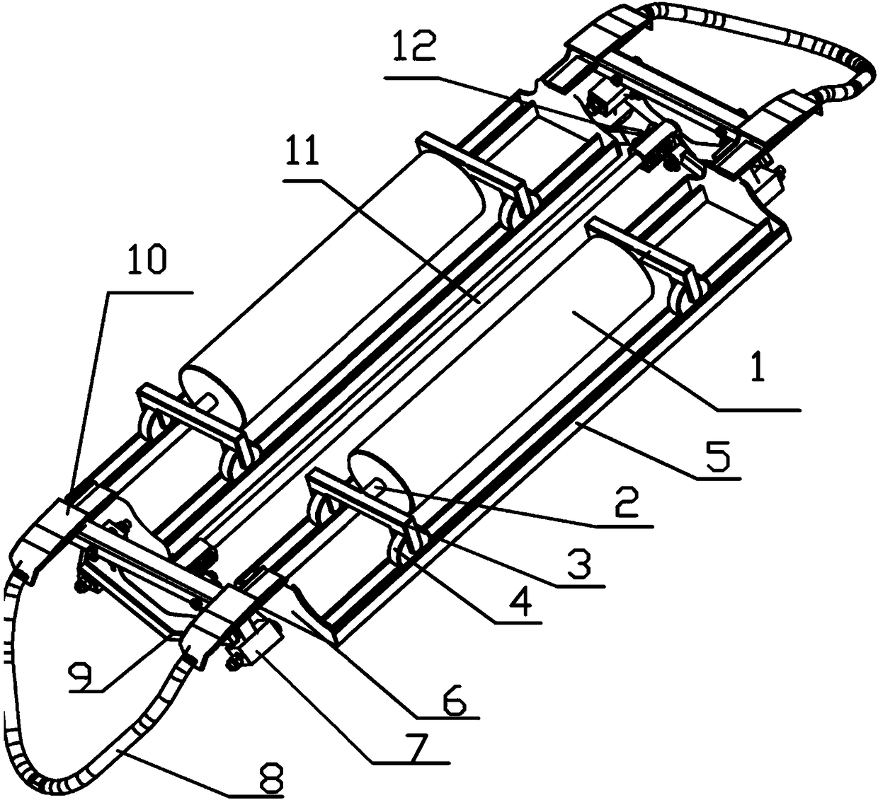
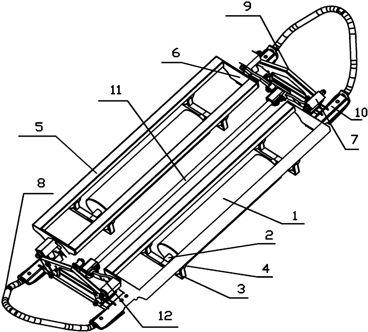
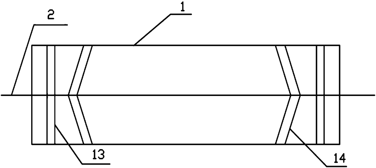

Image

  • Head of pantograph
  • Head of pantograph
  • Head of pantograph

Examples


Embodiment Construction

[0037] The invention provides a pantograph bow head. By improving the existing structure, the sliding friction between the sliding plate of the pantograph bow head and the contact line is avoided in the horizontal and vertical directions, and the distance between the pantograph and the catenary is significantly improved. The effect of current collection is also convenient for maintenance and repair, and the maintenance cost is reduced.

[0038] The following will clearly and completely describe the technical solutions in the embodiments of the present invention with reference to the accompanying drawings in the embodiments of the present invention. Obviously, the described embodiments are only some, not all, embodiments of the present invention. Based on the embodiments of the present invention, all other embodiments obtained by persons of ordinary skill in the art without making creative efforts belong to the protection scope of the present invention.

[0039] Such as Figur...


PUM


Abstract

The invention discloses a head of a pantograph. The head of the pantograph comprises a supporting structure, a roller structure and a connecting structure, wherein the roller structure can be contacted with a contact line to realize the conduction with the contact line, and the cylinder structure rolls in the axial direction of the contact line; and the connecting structure is used for connectingthe roller structure and the supporting structure, and the connecting structure enables the roller structure to move on the supporting structure in the radial direction of the contact line. Accordingto the head of the pantograph, the sliding friction between a sliding plate of the head of the pantograph and the contact line in the horizontal direction and longitudinal direction is avoided, the current collection effect between bow nets is greatly improved, and at the same time, the maintenance and overhaul are convenient, and the maintenance cost is reduced.

Description

technical field [0001] The invention relates to the technical field of electric traction locomotives, in particular to a pantograph head of electric traction locomotives. Background technique [0002] At present, the pantograph-catenary current collection method of electric traction locomotives (including subways, trams, etc.) is to realize the current collection through the sliding contact between the sliding plate of the pantograph head and the contact wire. The catenary is a fixed device, the locomotive is a mobile device, and the pantograph is fixed on the locomotive. Due to the movement of the locomotive, there is always a longitudinal (traveling direction of the locomotive, which is also the axial direction of the contact line) relative to the contact line of the sliding plate and the catenary. Sliding, at the same time, due to the influence of the locomotive’s lateral (mainly referring to the left and right direction of the locomotive, but also the radial direction of...

Claims


Application Information

Patent Timeline
IPC IPC(8): B60L5/20
CPCB60L5/205B60L2200/26
Inventor 袁文辉张波蒋忠城张彦林黄学君李军
Owner ZHUZHOU ELECTRIC LOCOMOTIVE CO
Learn More