Rake head special for eliminating furrows and construction technology of rake head

A rake head and ditch technology, applied in the field of raking and suction boats, can solve the problems of increasing the cost of the ship, reducing the construction efficiency, and reducing the output of the ship, and achieves the effects of improving the ground breaking capacity, facilitating the ground breaking and reducing the ridges and ditch.

Active Publication Date: 2021-08-13
CCCC GUANGZHOU DREDGING
View PDF6 Cites 0 Cited by
  • Summary
  • Abstract
  • Description
  • Claims
  • Application Information

AI Technical Summary

Problems solved by technology

[0006] In order to make up for the deficiencies of the existing technology and solve the problem that false sweeping will occur when the rake head performs the "ditch" elimination operation, resulting in a decrease in ship output, a decrease in construction efficiency, an increase in daily fuel consumption, and further increase in ship cost. A special rake head for eliminating furrows and its construction technology

Method used


Image

  • Rake head special for eliminating furrows and construction technology of rake head
  • Rake head special for eliminating furrows and construction technology of rake head
  • Rake head special for eliminating furrows and construction technology of rake head

Examples


Embodiment 1

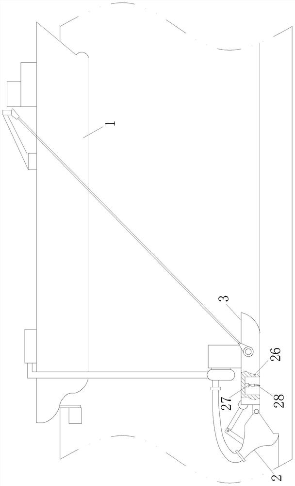
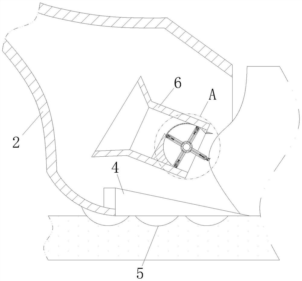
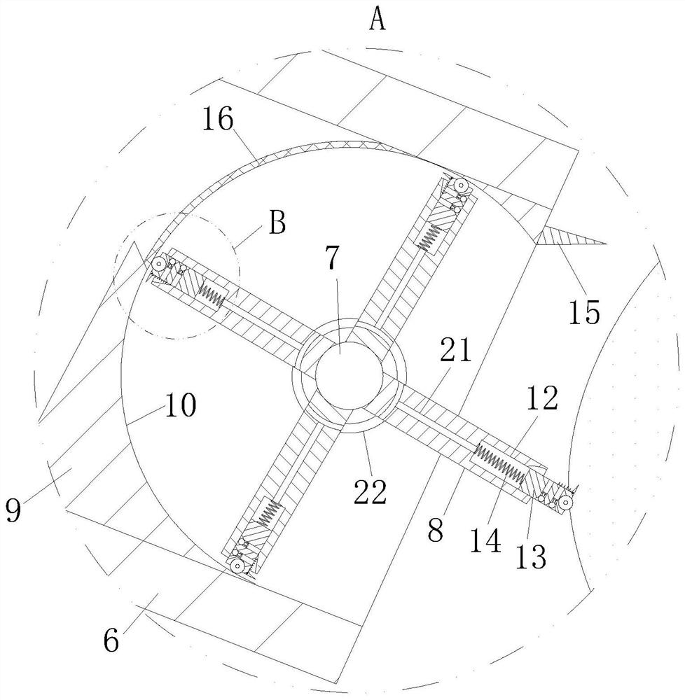
[0034] Such as Figure 1-Figure 4 As shown, a special rake head for eliminating ridges according to the present invention includes a hull 1 and a material pumping chamber 2, and a heel section 3 is provided on one side of the material pumping chamber 2; the inner bottom of the material pumping chamber 2 There are rake teeth 4 at the end, and a group of protrusions 5 are provided at the bottom of the rake teeth 4 and the pumping chamber 2. The inside of the pumping chamber 2 is provided with a partition chamber 6, and the partition chamber 6 is close to the pumping chamber 2. One side of the opening is rotatably connected with a rotating column 7, and a group of circularly uniformly distributed rotating plates 8 are connected to the side wall of the rotating column 7, and the side wall of the rotating column 7 is far away from the corresponding dividing chamber 6 of the opening side of the pumping chamber 2. The side wall is provided with a stopper 9, and one end of the stopper...

Embodiment 2

[0043] Such as Figure 5 As shown, compared with Example 1, the bottom end of the hydraulic rod 27 is provided with a transition chamber 29, the bottom end of the hydraulic rod 27 is connected with a piston 30 slidingly connected with the transition chamber 29, and the cutter 28 is installed in the transition chamber 29 At the bottom end, the two side walls of the cutter 28 are respectively provided with chute 31, the inside of the chute 31 is slidingly connected with cutting teeth 32, and an elastic member is connected between the cutting teeth 32 and the inner end of the chute 31 33, the inside of the cutter 28 is provided with an air flow groove 34 communicating with the transition chamber 29 and the chute 31, and the side wall of the cutter 28 is provided with an opening and closing groove 35 communicating with the air flow groove 34, and the opening and closing The opening and closing block 36 is slidably connected to the inside of the slot 35, and the outer end of the op...


PUM


Abstract

The invention belongs to the technical field of drag suction dredgers, and particularly relates to a rake head special for eliminating furrows and a construction technology of the rake head. The rake head comprises a boat body and a material pumping cavity. Rake teeth are arranged at the bottom end in the material pumping cavity, a set of protruding bodies is arranged on the rake teeth and at the bottom end of the material pumping cavity, a dividing cavity is formed in the material pumping cavity, one side of the dividing cavity is rotationally connected with a rotating column, the side wall of the rotating column is connected with rotating plates, a check block is arranged on the side wall of the dividing cavity, and a set of cutting knives is arranged at the outer end of each rotating plate. The protruding bodies are installed at the bottom of the rake head, the friction force between the rake head and furrow hard soil is increased, transverse sliding of the rake head is effectively reduced, and the aims of accurate shallow sweeping and furrow reduction are achieved; and meanwhile, the soil breaking capacity of the rake head to bed body silt can be improved through the arranged dividing cavity, the negative pressure in the material pumping cavity is used for driving the rotating plates to break hard soil, a complex electrical mechanism does not need to be additionally arranged for driving, and the use cost of a drag suction dredger is greatly reduced.

Description

technical field [0001] The invention belongs to the technical field of rake suction boats, in particular to a special rake head for eliminating ditches and its construction technology. Background technique [0002] The drag suction dredger is a ship that dredges from the seabed, and its dredging method is similar to that of a vacuum cleaner. The ship is equipped with a centrifugal pump, which is used to suck up water and mud from the seabed and discharge them into the mud tank of the ship. These operations are all carried out during the voyage, digging while sailing, and sailing to the mud dumping area when the mud tank is full; large-scale suction boats will encounter hard soil during construction on some engineering sites, due to poor construction quality control , prone to "ditch" phenomenon. [0003] In the prior art, there are also some technical solutions about the suction boat, such as a Chinese patent, the patent number is 2012800439855, which proposes a material (...

Claims


Application Information

Patent Timeline
Patent Type & Authority Applications(China)
IPC IPC(8): E02F5/30E02F5/28E02F3/88E02F3/90E02F3/92
CPCE02F5/30E02F5/305E02F5/28E02F3/88E02F3/8833E02F3/885E02F3/90E02F3/92E02F3/9256
Inventor 蒋祖聪
Owner CCCC GUANGZHOU DREDGING
Why Eureka
Try Eureka