
Metal rotating blade

A technology of rotating blades and blades, used in metal processing equipment, cutters for shearing machines, shearing devices, etc., can solve the problems that the blades cannot be rotated in metal cutting, the blades vibrate greatly, and the work is time-consuming, etc., to enhance the connection. performance and stability, enhanced connectivity, and the effect of preventing dust from falling in

Inactive Publication Date: 2018-06-19
李嘉顺
View PDF3 Cites 0 Cited by
  • Summary
  • Abstract
  • Description
  • Claims
  • Application Information

AI Technical Summary

Problems solved by technology

[0004] The purpose of the present invention is to provide a metal rotary blade to solve the problem that the blade in the above background technology has a large vibration during use, which makes the work time-consuming, causes noise pollution, and the blade cannot perform rotary cutting on metal, which brings great inconvenience to the metal cutting work. Here comes the question of limitations

Method used


Image

  • Metal rotating blade
  • Metal rotating blade
  • Metal rotating blade

Examples


Embodiment Construction

[0018] The following will clearly and completely describe the technical solutions in the embodiments of the present invention with reference to the accompanying drawings in the embodiments of the present invention. Obviously, the described embodiments are only some, not all, embodiments of the present invention. Based on the embodiments of the present invention, all other embodiments obtained by persons of ordinary skill in the art without making creative efforts belong to the protection scope of the present invention.

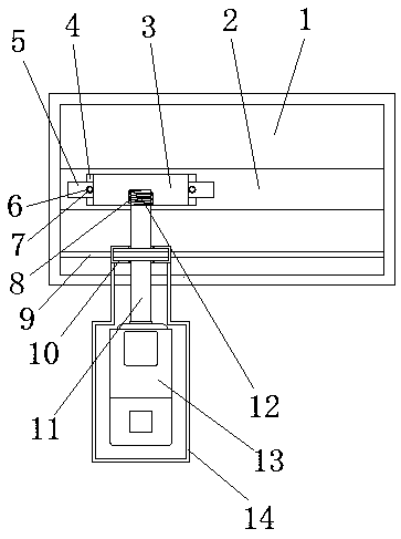
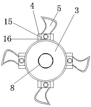
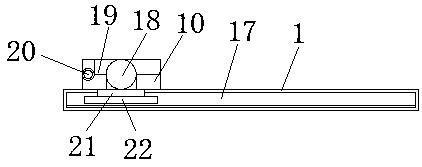
[0019] see Figure 1-3 , the present invention provides a technical solution: a metal rotary blade, including a rectangular workbench 1, a blade channel 2, a blade disc 3, a connecting block 4, a blade 5, a gasket 6, a bolt 7, an inner wire 8, a connecting rod channel 9. Fixed frame 10, rotating shaft 11, outer wire 12, motor 13, motor cover 14, card slot 15, nut hole 16, chute 17, rotating shaft hole 18, movable frame 19, movable shaft 20, connecting rod 21 a...


PUM

PropertyMeasurementUnit
Lengthaaaaaaaaaa

Abstract

The invention discloses a metal rotating blade. The metal rotating blade comprises a rectangular workbench, a blade and a movable frame, wherein a blade channel is arranged in the interior of the rectangular workbench, and a blade disc is connected to the inner side of the blade channel; a connecting block is fixed at the left end of the blade disc, and the inner wall of the bottom end of the blade disc is provided with an inner wire; the blade is located on the inner side of the connecting block, and a clamping groove is formed in the middle of the connecting block; a screw cap hole is formedin the inner side of the connecting block, a gasket is arranged on the inner wall of the blade, and a bolt is arranged in the gasket; a connecting rod channel is formed in the lower end of the rectangular workbench, and the inner side of the connecting rod channel is connected with a connecting rod; and a sliding plate is arranged at the bottom of the connecting rod, and a sliding groove is formed in the outer side of the sliding plate. According to the rotating blade for metal machining, the blade disc is arranged, and the outer side of the blade disc is attached to the inner wall of the blade channel, so that the blade can rotate on the inner side of the blade channel through the blade disc, and cutting is carried out on metal.

Description

technical field [0001] The invention relates to the technical field of metal processing devices, in particular to a metal rotary blade. Background technique [0002] With the rapid development of economy and the advancement of science and technology in various regions, all walks of life are inseparable from metal products, but metal products change from irregular metals to these products used in people's daily life, which is actually a long process of metal processing In the process of metal processing, the equipment that needs to be used includes metal processing blades, machine tools, grinding machines, etc. [0003] The blades on the market vibrate greatly during use, which makes the work time-consuming and causes noise pollution, and the blades cannot perform rotary cutting on metals, which brings limitations to metal cutting work. Therefore, we propose a metal rotary blade. Contents of the invention [0004] The purpose of the present invention is to provide a metal ...

Claims


Application Information

Patent Timeline
IPC IPC(8): B23D35/00
CPCB23D35/001
Inventor 李嘉顺
Owner 李嘉顺
Learn More