
Optical fiber connector capable of being assembled on site

An optical fiber connector and connector technology, applied in the directions of light guides, optics, instruments, etc., can solve the problems of incomplete optical fiber connection and weak optical fiber connectivity, and achieve the effect of simple structure and enhanced connectivity.

Active Publication Date: 2020-03-31
韩国奥特伦株式会社
View PDF11 Cites 0 Cited by
  • Summary
  • Abstract
  • Description
  • Claims
  • Application Information

AI Technical Summary

Problems solved by technology

[0006] Although the fiber optic connector disclosed in this document can be assembled on site, the fiber optic connector may have the disadvantage that the connectivity of the optical fibers may be relatively weak and the coupling of the optical fibers may not be complete because they The structure, that is, when the housing holder that closes the optical fiber housing cover moves, the optical fiber housing cover clamps the optical fiber due to the thickness difference of the optical fiber housing cover

Method used


Image

  • Optical fiber connector capable of being assembled on site
  • Optical fiber connector capable of being assembled on site
  • Optical fiber connector capable of being assembled on site

Examples


Embodiment Construction

[0064] In the following description, only the parts necessary for understanding the embodiments of the present disclosure will be described, and the description of other parts may be omitted so as not to obscure the subject matter of the present disclosure.

[0065] The terms and expressions used in the following description and appended claims do not have to be interpreted in ordinary or dictionary meanings, and may be appropriately defined herein to be used as terms to describe the present disclosure in the best possible manner. These terms and expressions should be interpreted as meanings and concepts consistent with the technical idea of ​​the present disclosure. Therefore, the embodiments described in this specification and the configurations shown in the drawings are merely preferred embodiments of the present disclosure, and are not intended to limit the scope of the present disclosure, and various equivalents and equivalents can be made according to the illustrated embodim...


PUM


Abstract

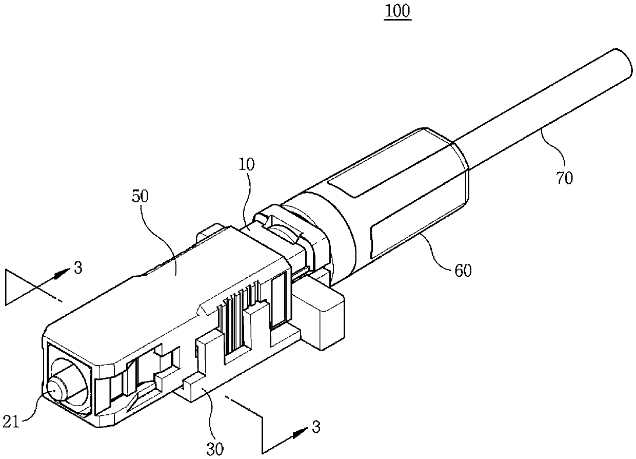
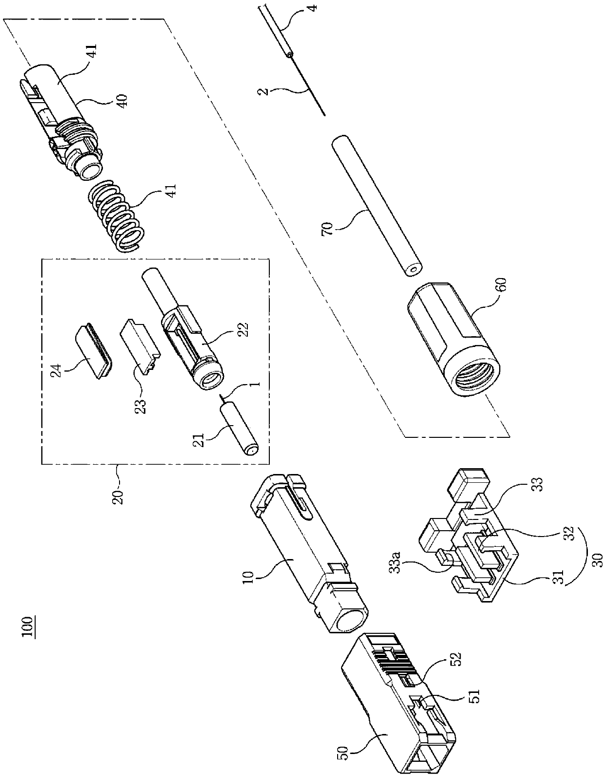
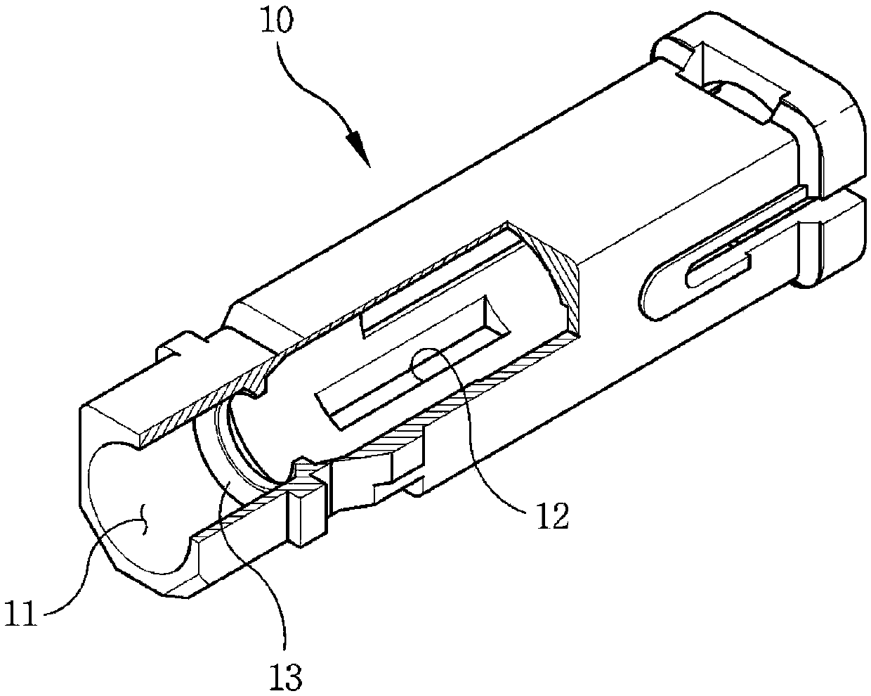
The present disclosure relates to an optical fiber connector capable of being assembled on site. The connector comprises: a connector body having a hole penetrating both ends and a first insertion port penetrating the lower portion thereof; a splicing unit that is inserted into the hole of the connector body, holds the first core, aligns with the first optical fiber or a second optical fiber provided to the outside, and elastically presses the first or second optical fiber in a state in which the first optical fiber contacts the second optical fiber; a jig coupled to the connector body throughthe first insertion port to release the pressing of the splicing unit; a holder unit coupled to the connector body to elastically support one end of the splice unit and provide access to the second optical fiber, the other end of the splice unit being supported by the connector body; a universal tube formed of an elastic material and surrounding an outer surface of the coating layer or the outersheath of the second optical fiber and inserted into the holder unit; and a boot coupled to the holder unit to fasten the universal pipe.

Description

Technical field [0001] The present disclosure relates to an optical fiber connector, and more specifically, to a field-assembled optical fiber connector that can be simply assembled on site to connect optical fibers. Background technique [0002] An optical fiber connector is a device used to join two optical fibers together. In view of the complexity of the connection process, most of the processes are usually carried out in manufacturing facilities. This process includes aligning the core of the optical fiber with a ferrule, polishing the end of the optical fiber and epoxy bonding to cause optical loss Minimized, connectors are attached to the two ends of the optical fiber to form a so-called "patch cord" that is distributed and used for optical line installation. For example, LC, ST, FC and SC fiber optic connectors are currently used. [0003] Since the patch cord is manufactured in the form of a finished product with a certain length in the manufacturing facility according t...

Claims


Application Information

Patent Timeline
IPC IPC(8): G02B6/38
CPCG02B6/3838G02B6/3858
Inventor 尹成真朴瓒烨金熙珉韩东熙
Owner 韩国奥特伦株式会社
Learn More